DIY Mini Interferometer
It also makes sounds
Introduction
 Michelson interferometers are based on the principle of division of amplitude, that is, an incident beam of light falling on a beam splitter splits into two parts of equal intensity. This is achieved by using a beam splitter which reflects one half of the intensity on one direction and transmits the other half.
The two beams, traveling through different paths, are then recombined on the screen to obtain the interference pattern. This interference is determined by the differential arm length, that is, the difference in lengths of the optical paths in the two arms through which the beams traverse. The following prototype of the interferometer works in the same principles.
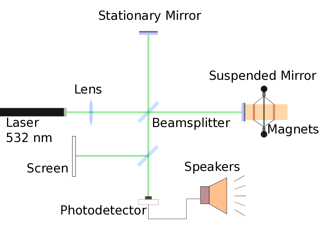
A laser emitting in the visible spectrum (around 540 nm) acts as the spatially and temporally coherent light source. After being divided at the beam splitter, one of the beams traverses to reflect from the stationary mirror. Theohter beam, on the other hand travels down the arm to encounter a suspended mirror. The longitudinal motion of the mirror caused by distrubances slightly changes the path length of this beam. This suspended mirror can easily lose alignment due to the excess oscillations due to disturbances. To reduce this, the principles of magnetic or eddy current damping are employed. The mirror is mounted on a copper tube which is itself suspended via copper wires in a magnetic field. The wires are so chosen due to their tensile strength; additionally due to being metallic, they also add to the damping. After reflection from the mirrors at the end of the respective arms, the light beams from both arms reach the beam splitter again to combine and yield a recombined beam which is projected onto the screen. The relative path difference of the two beams decides the phase relation between them at the screen and subsequently determines whether light or dark fringes are expected. If the two light beams are in phase at the screen, that is, if peaks corresponding to their maxima and minima occur simultaneously, a bright fringe maybe observed on the screen, whereas if the maxima of one beam corresponds to a minima of the other, dark fringes are observed. In addition to just visual observation, the interference of the two light waves can be verified by transforming the light interference to the auditory domain! The oscillating path difference will translate into a time varying intensity of light on the center of the fringe pattern which can be converted to voltage by a photodetector. The oscillating voltage can be then applied to a speaker in order to obtain an audio signal.
Michelson interferometers are based on the principle of division of amplitude, that is, an incident beam of light falling on a beam splitter splits into two parts of equal intensity. This is achieved by using a beam splitter which reflects one half of the intensity on one direction and transmits the other half.
The two beams, traveling through different paths, are then recombined on the screen to obtain the interference pattern. This interference is determined by the differential arm length, that is, the difference in lengths of the optical paths in the two arms through which the beams traverse. The following prototype of the interferometer works in the same principles.
A laser emitting in the visible spectrum (around 540 nm) acts as the spatially and temporally coherent light source. After being divided at the beam splitter, one of the beams traverses to reflect from the stationary mirror. Theohter beam, on the other hand travels down the arm to encounter a suspended mirror. The longitudinal motion of the mirror caused by distrubances slightly changes the path length of this beam. This suspended mirror can easily lose alignment due to the excess oscillations due to disturbances. To reduce this, the principles of magnetic or eddy current damping are employed. The mirror is mounted on a copper tube which is itself suspended via copper wires in a magnetic field. The wires are so chosen due to their tensile strength; additionally due to being metallic, they also add to the damping. After reflection from the mirrors at the end of the respective arms, the light beams from both arms reach the beam splitter again to combine and yield a recombined beam which is projected onto the screen. The relative path difference of the two beams decides the phase relation between them at the screen and subsequently determines whether light or dark fringes are expected. If the two light beams are in phase at the screen, that is, if peaks corresponding to their maxima and minima occur simultaneously, a bright fringe maybe observed on the screen, whereas if the maxima of one beam corresponds to a minima of the other, dark fringes are observed. In addition to just visual observation, the interference of the two light waves can be verified by transforming the light interference to the auditory domain! The oscillating path difference will translate into a time varying intensity of light on the center of the fringe pattern which can be converted to voltage by a photodetector. The oscillating voltage can be then applied to a speaker in order to obtain an audio signal.
What you need
Laser
A green laser, preferably externally powered. Can be bought online.
Optics
- 2 X Mirrors
- 2 X Beamsplitters
- 1 X Lens Just as with the beamsplitter, we can also find cheap alternatives for laboratory standard lenses.
- Screen Any piece of paper would do
Mirrors of an appropriate dimension can be bought online cheaply
While a laboratory standard 50-50 beamsplitter can be very expensive, a phone screen protector can serve as a cheap and sturdy alternative.
Suspension
- Copper Tube as counterweight for mirror. Plasticine can be added to the tube in order to balance the suspension at a desired angle
- Suspension Wires (Copper) Easily available in any electronics store
- Magnets for damping
Mounts
In order to align the apparatus properly, it would be preferable to have custom-made mounts for the optics. Suggested designs (3D-printable) have been detailed later in the page.
Electronics
For the photodetector, we would need to construct a trans-impendance amplifier circuit with the following components
- Photodiode A silicon photodiode is preferable for this purpose as it is sensitive in the visible region.
- Op-Amp (OP-27G) Can be bought in any electronics store.
- Resistors + Capacitors + Wires Also available in any electronics store.
- Speakers for output
- Batteries (Lot of them)
Base
Metallic Butcher TrayPhotodetector Circuit
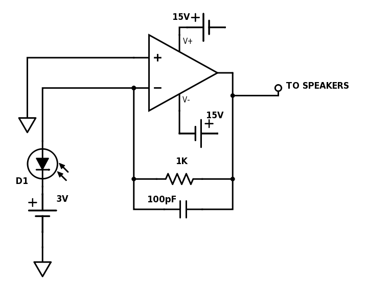
The 3V bias and 15V rail voltages can be obtained using AA batteries in series
Mount Designs
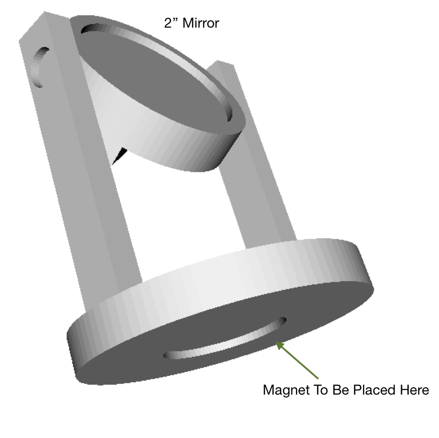
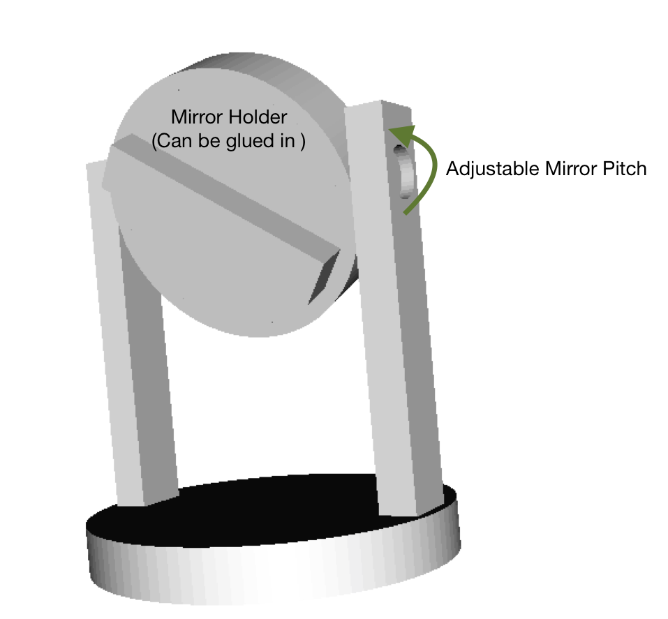
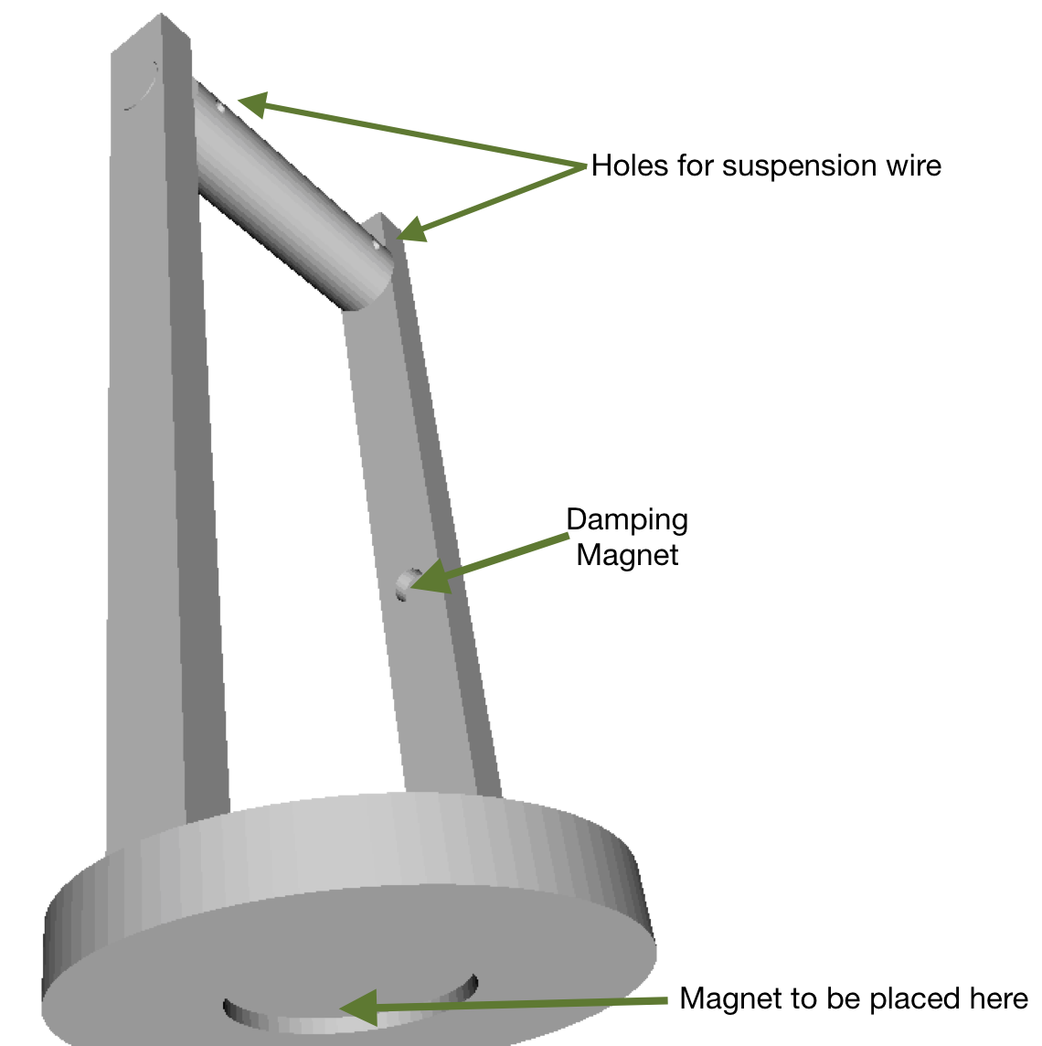
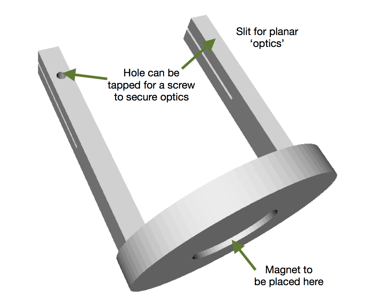
For all the mounts, we have created a slot for a neodymium magnet that can be used to secure the mount to the metallic base. Erasers can be glued on to the bottom of the base in order to provide seismic isolation.Mirror Mount
Suspension
Mount for beamsplitter and lens
STL files for 3D printing mounts :
File units are inchesMirror Mount
Suspension Mount
Beam Spiltter and Lens Mount
Cost Table
| Item | Price |
|---|---|
| Laser | $24.7 |
| Mirrors | $0.50 for 2 |
| Lens | $0.60 |
| Beamsplitter | $0.99 |
| Magnets | $12 |
| Batteries | $13 |
| Photodiode | $5.21 |
| Op-Amp+Resistors+Capacitors | $4 |
| Speakers | $13.56 |
| Screen | ~$0 |
| Wires | $1 |
| Copper Tube | $3.34 |
| Plasticine | ~$2 |
| Base | $16 |
| 3D-Printed Stuff | ? |
| $96.9 + 3D Printing costs |