Optical Enhancement Cavities for Laser Fusion
Develop high-finesse optical enhancement cavities to recycle and shape laser pulses for inertial fusion and high-energy-density physics.
Gallery
Research area
The National Ignition Facility achieved fusion ignition in 2022 — by firing 192 laser beams that fill a building. For fusion to become a power source, we need to compress targets at 10 Hz using systems that fit in a power plant. The laser is the bottleneck: NIF’s flashlamp-pumped Nd:glass amplifiers deliver 2 MJ per shot but fire only a few times per day and convert under 1% of their wall-plug energy to light on target.
What if most of the laser light could be recycled? An optical enhancement cavity (OEC) — the same resonant technology that builds up laser power in LIGO — could capture and reuse the light that doesn’t couple to the fuel capsule, reducing the required laser energy per shot by an order of magnitude or more. This is the central idea of our DOE INFUSE collaboration with Blue Laser Fusion (BLF).
Contents:
- The laser fusion energy problem
- Fabry-Perot physics at fusion scale
- Coherent beam combining
- Thermal management at megawatt circulating power
- Pulse shaping in an enhancement cavity
- Competing approaches to high-rep-rate fusion
- The DOE INFUSE program
- EGG contributions
- Current status
- Key references
The laser fusion energy problem
NIF demonstrated that laser-driven inertial confinement fusion (ICF) works: 2.05 MJ of UV laser light compressed a deuterium-tritium capsule to conditions where fusion reactions released 3.15 MJ — a target gain $G \approx 1.5$ (Abu-Shawareb et al. 2024). But a power plant requires the product of driver efficiency and target gain to exceed a threshold: $\eta_d \times G > 10$. With realistic driver efficiencies of $\eta_d \approx 10\%$, this demands target gains $G > 100$ — roughly two orders of magnitude beyond what NIF achieved (Hurricane et al. 2023). NIF was designed as a weapons-physics facility, not a power plant, and its architecture faces three fundamental limitations for energy production:
-
Repetition rate. NIF fires once every several hours. A fusion power plant requires ~10 Hz — tens of thousands of shots per day. Flashlamp-pumped Nd:glass amplifiers cannot be cooled fast enough for this duty cycle.
-
Wall-plug efficiency. NIF consumes ~400 MJ of electrical energy to produce 2 MJ of laser light — a wall-plug-to-target efficiency of ~0.5%. A power plant needs >10% to close the energy balance, even with target gains of 50–100.
-
Cost per joule. NIF’s 192-beam laser system cost ~$3.5 billion. Scaling laser energy by brute force — simply building bigger lasers — is economically impractical.
NIF uses indirect drive: the lasers illuminate the inside of a gold hohlraum that radiates X-rays onto the capsule. This simplifies illumination uniformity but wastes ~85% of the laser energy in X-ray conversion. Direct drive — illuminating the capsule directly with laser beams — is more efficient but demands exquisite beam uniformity and pulse shaping. The OEC concept is compatible with both approaches, but the pulse-shaping requirements differ significantly (see below).
The OEC concept attacks all three problems simultaneously. By recycling the ~90% of laser light that is not absorbed by the target, the required fresh laser energy per shot drops by roughly an order of magnitude. Smaller lasers are cheaper, more efficient, and easier to run at high repetition rates.
Fabry-Perot physics at fusion scale
An optical enhancement cavity is a Fabry-Perot resonator: two or more mirrors arranged so that light bounces back and forth, constructively interfering on each round trip. The circulating power builds up to a level set by the mirror reflectivities and the round-trip losses.
Power buildup
For a two-mirror cavity with input coupler reflectivity $R_1$ and all other losses (including the second mirror, scattering, absorption, and target coupling) lumped into a round-trip loss $L_\text{RT}$:
\[P_\text{circ} = P_\text{in} \times \frac{T_1}{\left(1 - \sqrt{R_1(1 - L_\text{RT})}\right)^2}\]where $T_1 = 1 - R_1$ is the input coupler transmission. Maximum buildup occurs at impedance matching: $T_1 = L_\text{RT}$. At this operating point, the buildup factor simplifies to:
\[\mathcal{G} = \frac{P_\text{circ}}{P_\text{in}} = \frac{1}{L_\text{RT}}\]Numerical example: LIGO vs. fusion cavity
LIGO arm cavity: $L_\text{RT} \approx 75$ ppm (dominated by the end mirror transmission of ~5 ppm, plus scatter and absorption). Buildup factor $\mathcal{G} \approx 300$. Input power ~40 W yields ~750 kW circulating.
Fusion OEC target: $L_\text{RT} \approx 1\%$ (dominated by target coupling — the fraction of light absorbed or scattered by the fuel capsule per pass). Buildup factor $\mathcal{G} \approx 100$. Input power ~10 kW yields ~1 MW circulating.
The cavity finesse is lower than LIGO ($\mathcal{F} \approx 300$ vs. $\mathcal{F} \approx 450$), but the absolute circulating power is 1000x higher. This creates thermal management challenges that have no precedent in precision measurement — but the basic cavity physics is identical.
Impedance matching: why perfect coupling requires loss equal to transmission
The reflected field from a Fabry-Perot cavity is the coherent sum of the promptly reflected beam and the leakage field from inside the cavity. These two contributions have opposite sign. The reflected amplitude is:
\[E_r = r_1 E_\text{in} - \frac{t_1^2 \, r_\text{eff}}{1 - r_1 \, r_\text{eff}} \, E_\text{in}\]where $r_\text{eff} = r_2(1 - L)^{1/2}$ is the effective round-trip reflection amplitude (excluding the input coupler) and $L$ accounts for all intra-cavity losses. Setting $E_r = 0$ gives the impedance-matched condition: $r_1 = r_\text{eff}$, or equivalently $T_1 = L_\text{RT}$. At this point, all incident power enters the cavity and none is reflected — the input coupler transmission exactly equals the round-trip loss.
The physical implication is that the OEC designer must know the target coupling loss (the fraction of light absorbed or scattered by the fuel capsule per pass) before choosing the input coupler reflectivity. If the target coupling changes shot-to-shot, the cavity is no longer impedance-matched and the buildup factor drops. This motivates active control of the input coupler transmission — a capability that does not exist in LIGO but may be essential for fusion OECs.
Cavity linewidth and pulse compatibility
The cavity stores light efficiently only within its resonance linewidth:
\[\delta\nu = \frac{\text{FSR}}{\mathcal{F}} = \frac{c}{2nL \cdot \mathcal{F}}\]For a 1 m cavity with finesse 300, $\delta\nu \approx 500$ kHz. This is narrowband — far too narrow for femtosecond pulses (which span terahertz of bandwidth) but well matched to nanosecond-scale shaped pulses used in indirect-drive ICF. The pulse duration must satisfy $\tau_\text{pulse} \gg 1/\delta\nu$ for efficient cavity coupling, which for our parameters means pulses longer than ~2 µs couple efficiently.
For shorter pulses, one can operate the cavity in a pulse-stacking mode: the input pulse train is synchronized to the cavity round-trip time, and successive pulses add coherently inside the cavity. This is related to the enhancement cavity techniques used in high-harmonic generation with femtosecond lasers (Jones et al. 2005).
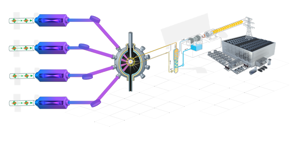
Coherent beam combining
A single fiber laser produces ~1–10 kW of continuous-wave power. Reaching the ~10 kW injection power needed for an OEC with $\mathcal{G} \sim 100$ requires coherent beam combining (CBC) — phase-locking multiple laser amplifiers so their outputs add constructively into a single beam.
CBC has been demonstrated at multi-kW levels by the defense and industrial laser communities. The key requirement is maintaining the relative phase of all channels to within a fraction of a wavelength ($\lambda/10$ or better). This is achieved by:
- Seed splitting: A single master oscillator is split into $N$ channels, each feeding a fiber amplifier. All channels share the same frequency and initial phase.
- Phase sensing: The combined beam is sampled, and a phase error signal is derived for each channel (typically via dithering or heterodyne detection).
- Active correction: Electro-optic or piezoelectric actuators in each channel adjust the optical path length to maintain constructive interference at the combining element.
The BLF architecture combines four fiber amplifier channels into the OEC. Scaling to higher power requires more channels — a well-understood engineering challenge in the directed-energy community (Fan 2005).
Phase noise budget for multi-channel CBC
Maintaining coherent combination at the $\lambda/10$ level requires controlling several independent noise sources in each fiber channel:
- Fiber thermal expansion. Ambient temperature fluctuations change the optical path length of each fiber amplifier. For a 10 m fiber with $dn/dT \approx 10^{-5}$/K, a 1 mK temperature fluctuation produces ~100 nm of path length change — comparable to $\lambda/10$. Active stabilization bandwidth must exceed the thermal fluctuation rate (~1 Hz).
- Acoustic and vibrational pickup. Mechanical vibrations couple to fiber path length via strain-optic effects. Proper routing, damping, and enclosure reduce acoustic noise, but active phase correction remains essential at the ~kHz level.
- Laser frequency noise. Since all channels derive from the same master oscillator, frequency noise is common-mode and cancels in the combining process — this is a major advantage of seed-splitting architectures.
- Amplifier gain fluctuations. Pump power variations cause amplitude and phase modulation of the amplified signal. These fluctuations are typically slow (sub-kHz) and can be suppressed by feedback to the pump diode current.
The required control bandwidth is set by the fastest of these noise sources, typically acoustic pickup in the low kHz range. Modern CBC systems routinely achieve >95% combining efficiency with bandwidths of a few kHz (Muller et al. 2024).
Thermal management at megawatt circulating power
The defining engineering challenge for fusion OECs is thermal management. Even with state-of-the-art mirror coatings (absorption < 1 ppm per surface), a cavity circulating 1 MW deposits ~1 W per mirror — enough to cause significant thermal lensing and wavefront distortion in the mirror substrates.
Mirror absorption and thermal lensing
When a high-reflectivity dielectric coating absorbs a fraction $\alpha$ of the incident power, the resulting temperature gradient creates a refractive index variation (thermal lens) in the substrate. For a Gaussian beam of power $P$ and spot size $w$, the thermal focal length scales as:
\[f_\text{th} \approx \frac{\pi \kappa w^2}{P \cdot \alpha \cdot (dn/dT)}\]where $\kappa$ is the thermal conductivity and $dn/dT$ is the thermo-optic coefficient. For fused silica at 1 MW circulating power with $\alpha = 0.5$ ppm and $w = 5$ mm, $f_\text{th}$ can be comparable to the cavity length — meaning thermal lensing fundamentally alters the cavity eigenmode.
This is a familiar problem in LIGO, where thermal compensation systems (CO$_2$ laser heating of ring heaters and compensation plates) actively correct thermally induced aberrations (Brooks et al. 2016). The same approach applies to fusion cavities, but at higher thermal loads. Our group’s experience with LIGO adaptive optics and precision optical coatings maps directly onto this challenge.
A key diagnostic technique developed for LIGO is in-situ thermal state characterization via higher-order mode tracking: by monitoring how the resonance frequencies of higher-order transverse modes shift as the cavity heats up, one can reconstruct the thermal lens profile in real time without interrupting cavity operation (Mueller et al. 2015). This technique is directly applicable to fusion OECs, where the thermal state changes dynamically between shots and must be tracked to maintain optimal mode matching.
Mirror damage thresholds
At MW-level circulating power, the peak fluence on cavity mirrors approaches the laser-induced damage threshold (LIDT) of dielectric coatings. For nanosecond pulses at 1 µm, typical LIDT values are 10–50 J/cm$^2$, depending on coating design and surface quality. Designing cavity geometries that keep the fluence below LIDT while maintaining a stable eigenmode is a central constraint.
Coating damage mechanisms: fluence, defects, and photon densities
Mirror damage in high-power cavities operates through different mechanisms depending on the temporal regime:
Nanosecond regime (pulsed ICF operation). Damage is primarily defect-initiated: nanoscale absorbing inclusions or nodules in the coating heat faster than the surrounding dielectric can conduct heat away, creating localized plasma that ablates the coating. The damage threshold depends on defect density and size distribution, not bulk material properties. Typical values for ion-beam-sputtered coatings at 1064 nm are 10–50 J/cm² for nanosecond pulses, with careful substrate preparation and coating process control pushing toward the upper end.
CW regime (steady-state cavity operation between shots). Damage is absorption-driven: even sub-ppm absorption in high-quality coatings deposits enough power at MW circulating levels to create thermal runaway if contaminants (hydrocarbons, dust) are present on the surface. A single 10 µm dust particle absorbing 1% of the local intensity at 1 MW/cm² absorbs ~10 W — enough to carbonize and initiate a growing damage site. This motivates operating cavity mirrors in high vacuum with stringent cleanliness protocols.
Design strategy. Increase the beam spot size on mirrors to reduce fluence (larger mirrors, longer cavities), use substrates with high thermal conductivity (sapphire or silicon rather than fused silica), and apply global optimization techniques to the multilayer coating design to minimize electric field intensity at layer interfaces where defects concentrate (Venugopalan et al. 2024).
Pulse shaping in an enhancement cavity
Indirect-drive ICF (the NIF approach) requires carefully shaped laser pulses: a low-intensity “foot” lasting ~10 ns to launch initial shocks, followed by a high-intensity “main drive” that compresses the fuel to ignition conditions. The temporal shape of this pulse critically affects whether the fuel ignites.
An enhancement cavity acts as a linear filter with a transfer function set by its finesse and round-trip time. In the frequency domain:
\[H(\omega) = \frac{t_1}{1 - r_1 r_2 \, e^{i\omega \tau_\text{RT}}}\]where $\tau_\text{RT} = 2L/c$ is the round-trip time and $t_1$, $r_1$ are the input coupler amplitude transmission and reflection. The cavity smooths and stretches the input pulse — the circulating field cannot change faster than the cavity storage time $\tau_s = \mathcal{F} \cdot \tau_\text{RT}/\pi$.
For a finesse-300 cavity with 1 m length, $\tau_s \approx 300$ ns. This means the cavity naturally integrates sub-microsecond features in the input pulse. Achieving the precisely shaped pulses needed for ICF requires pre-compensating the input waveform to account for the cavity transfer function — essentially solving $E_\text{in}(t) = H^{-1} \ast E_\text{target}(t)$. This is a well-posed inverse problem as long as the target pulse has no features faster than $1/\tau_s$.
Solving the inverse pulse-shaping problem
Given the cavity transfer function $H(\omega)$ and the desired intracavity pulse shape $E_\text{target}(t)$, the required input field is obtained by frequency-domain inversion:
\[E_\text{in}(\omega) = \frac{E_\text{target}(\omega)}{H(\omega)}\]| This division amplifies any frequency components where $ | H(\omega) | $ is small — specifically at frequencies far from the cavity resonances. In practice, the target pulse bandwidth must be confined within the cavity linewidth to avoid requiring unphysically large input amplitudes. |
For real-time implementation, the inverse filter is discretized as a finite impulse response (FIR) pre-emphasis filter applied to the input waveform. The FIR coefficients are computed from the known cavity parameters (finesse, length, loss). The physical implementation uses an arbitrary waveform generator (AWG) driving an acousto-optic modulator (AOM) or electro-optic modulator (EOM) to sculpt the seed laser amplitude before amplification.
This is analogous to feedforward noise cancellation in LIGO, where known transfer functions are inverted to pre-compensate for the instrument response. The key difference is that LIGO feedforward operates continuously, while fusion pulse shaping operates on a shot-by-shot basis — each pulse can be individually optimized based on the current cavity state.
Competing approaches to high-rep-rate fusion
The OEC approach is not the only path to laser fusion energy. Several alternative strategies are being pursued by the growing commercial fusion sector.
Direct-drive with diode-pumped solid-state lasers (DPSSLs)
Replace NIF’s flashlamp-pumped Nd:glass with diode-pumped amplifiers that can operate at 10+ Hz. The HAPLS system at ELI Beamlines demonstrated 30 J at 3.3 Hz — but scaling to the MJ level at high rep rate remains a major engineering challenge. The gap between demonstrated DPSSL performance (~100 J) and the energy required for ignition (~1 MJ) spans four orders of magnitude. DPSSLs address the repetition rate problem but not the wall-plug efficiency problem (still ~10% at best), and the cost per joule decreases only slowly with diode pump technology improvements.
Magnetized target fusion
Use magnetic fields to slow thermal conduction in the fuel, reducing the laser energy required for ignition by 10–100x. General Fusion pursues a mechanical compression approach where pistons drive a liquid-metal liner onto a magnetized plasma target. This relaxes the laser requirements substantially but introduces new plasma physics challenges: maintaining the magnetic field topology during compression, preventing Rayleigh-Taylor instabilities at the liner-plasma interface, and achieving sufficient confinement time in the compressed state.
Z-pinch and pulsed power
Sandia’s Z machine uses pulsed electrical power (26 MA, 100 ns) rather than lasers to compress fusion fuel via magnetic pressure. This avoids the laser bottleneck entirely but faces its own repetition rate challenges — Z fires roughly once per day, limited by the time needed to replace the destroyed transmission lines. Zap Energy is developing a compact sheared-flow z-pinch that could operate at higher repetition rates by stabilizing the plasma magnetically rather than through wall confinement.
Laser-driven proton/ion beams
Use a short-pulse laser to accelerate ions via target normal sheath acceleration (TNSA), which then deposit their energy in pre-compressed fuel (fast ignition variants). This decouples the compression and ignition phases, potentially reducing the total laser energy needed. However, it requires ultra-intense lasers (>10$^{18}$ W/cm$^2$) and precise timing between the compression and ignition pulses — the ignitor beam must arrive within ~20 ps of peak compression.
Enhancement cavities for high-harmonic generation
The highest-repetition-rate OECs currently in operation serve a different community: high-harmonic generation (HHG). Femtosecond enhancement cavities build up peak intensities sufficient to drive nonlinear frequency conversion in intracavity gas jets, producing coherent extreme ultraviolet (XUV) radiation at MHz repetition rates. Carstens et al. (2014) achieved 72 kW average power in a femtosecond enhancement cavity — the highest average power demonstrated in any OEC to date. The physics differs from fusion OECs (femtosecond pulses, plasma dispersion from ionized gas, different spectral regimes) but the thermal management challenges are closely related: mirror absorption, thermally induced wavefront distortion, and damage at high intracavity fluence. The HHG community’s experience with high-power cavity operation provides the closest experimental precedent for MW-class cavity design.
Why the OEC approach is distinctive
The OEC concept is uniquely synergistic with existing laser technology: it takes any high-rep-rate laser system — fiber, DPSSL, or future architectures — and multiplies its effective energy by the cavity buildup factor. It is an accelerant for other approaches, not a competitor. If a 10 kW laser can do the work of a 100 kW laser, the engineering, cost, and thermal management problems all become dramatically more tractable.
The DOE INFUSE program
This project is funded through the DOE Innovation Network for Fusion Energy (INFUSE) program, which supports collaborations between fusion energy companies and national laboratories or universities. INFUSE awards are competitively selected and reviewed annually.
Our INFUSE award pairs Blue Laser Fusion — a startup developing laser-driven ICF for commercial energy — with the Caltech Experimental Gravity Group, bringing LIGO’s precision optical engineering to bear on a critical bottleneck in laser fusion.
EGG contributions
The Caltech EGG group brings two decades of precision cavity experience from gravitational-wave detection. The specific techniques and tools that transfer to fusion OECs include:
-
Cavity metrology techniques. In-situ measurement of free spectral range and transverse mode spacing for precision cavity characterization — essential for verifying that the OEC eigenmode matches the design (Stochino et al. 2012).
-
In-situ thermal state characterization. Tracking higher-order mode resonance frequencies to reconstruct the thermal lens profile in real time, enabling active thermal compensation without interrupting cavity operation (Mueller et al. 2015).
-
Global coating optimization. Particle swarm optimization combined with Markov chain Monte Carlo sampling for multilayer dielectric coating design — directly applicable to designing fusion OEC mirrors that minimize absorption while meeting reflectivity and damage threshold requirements (Venugopalan et al. 2024).
-
Photothermal noise in crystalline coatings. Characterization of coherent photothermal noise cancellation in AlGaAs/GaAs Bragg mirrors — a candidate material system for high-power, low-loss mirrors where conventional ion-beam-sputtered coatings approach their absorption limits (Chalermsongsak et al. 2016).
-
Mode matching characterization. Heterodyne detection technique for precision measurement of mode-matching efficiency into optical cavities — critical for maximizing the coupling of the combined beam into the OEC (Mueller et al. 2000).
-
Mirror birefringence analysis. Analysis of birefringence-induced polarization rotation and its fluctuations in high-finesse cavities — relevant to fusion OECs where stress-induced birefringence from thermal gradients can degrade interference contrast (Michimura et al. 2024).
-
Cavity-enhanced nonlinear optics. Our SFG project demonstrates cavity-enhanced nonlinear processes — managing thermal effects, maintaining resonance, and preserving beam quality under high circulating power.
The OEC project represents a compelling technology transfer: fundamental cavity science developed for basic physics (gravitational-wave detection) finding application in applied energy (fusion power). The physics is the same — only the scale changes. The initial design and characterization of the EGG/BLF OEC prototype is reported in Pattison et al. (2025, DOI:10.1364/OE.575181).
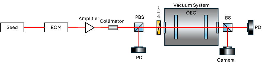
Current status
Prototype commissioning (2025). The first-generation OEC prototype is operational in the EGG lab. The system consists of a seed laser, fiber amplifier, mode-matching telescope, and a two-mirror Fabry-Perot cavity enclosed in a vacuum chamber. Initial measurements are characterizing the cavity finesse, mode matching efficiency, and lock stability (Pattison et al. 2025).
Near-term goals:
- Demonstrate cavity buildup factor > 100 at kW-class circulating power
- Characterize thermal lensing and wavefront distortion as a function of circulating power
- Deploy in-situ thermal diagnostics via higher-order mode tracking to monitor the cavity thermal state between shots
- Implement and test active thermal compensation
- Integrate coherent beam combining with cavity injection
Open questions:
- Scaling from CW to pulsed operation: LIGO operates in continuous wave; fusion requires pulsed or quasi-CW operation. How does the cavity locking and thermal equilibrium change in pulsed mode?
- Target debris and cavity protection: Each fusion shot produces debris that threatens the cavity mirrors. Mitigation strategies (sacrificial windows, gas curtains, magnetic deflection) must be compatible with low cavity loss.
- Coating survivability at MW fluence: Can the sub-ppm absorption coatings developed for LIGO survive the peak fluences in a fusion OEC? Damage mechanisms at high average power and high peak fluence are not fully characterized.
- Cavity locking recovery after fusion shots: Each fusion shot disrupts the cavity thermal equilibrium. The lock must reacquire in <100 ms for 10 Hz operation — comparable to the lock acquisition challenge in LIGO after seismic disturbances, but with additional thermal transients.
- Scaling the buildup factor: Higher buildup means lower required laser power but also tighter tolerances on losses and alignment. What is the practical upper limit?
Key references
Fusion and ICF context
- Abu-Shawareb et al., “Achievement of target energy gain larger than unity in an inertial fusion experiment,” PRL 132, 065102 (2024). DOI:10.1103/PhysRevLett.132.065102 — NIF ignition result.
- Nuckolls et al., “Laser compression of matter to super-high densities: thermonuclear (CTR) applications,” Nature 239, 139 (1972). DOI:10.1038/239139a0 — Original ICF concept.
- Lindl et al., “The physics basis for ignition using indirect-drive targets on the National Ignition Facility,” Phys. Plasmas 11, 339 (2004). DOI:10.1063/1.1578638 — Canonical indirect-drive ICF review.
- Hurricane et al., “Physics principles of inertial confinement fusion and U.S. program overview,” Rev. Mod. Phys. 95, 025005 (2023). DOI:10.1103/RevModPhys.95.025005 — Post-ignition program review.
Enhancement cavity physics
- Jones et al., “Femtosecond pulse amplification by coherent addition in a passive optical cavity,” PRL 94, 193201 (2005). DOI:10.1103/PhysRevLett.94.193201 — Enhancement cavity pulse stacking for high-harmonic generation.
- Carstens et al., “Megawatt-scale average-power ultrashort pulses in an enhancement cavity,” Optica 1, 457 (2014). DOI:10.1364/OPTICA.1.000457 — 72 kW average power in a femtosecond enhancement cavity.
- Siegman, Lasers (University Science Books, 1986) — Standard reference for Fabry-Perot theory, Gaussian beam optics, and cavity design.
Coherent beam combining
- Fan, “Laser beam combining for high-power, high-radiance sources,” IEEE J. Sel. Top. Quantum Electron. 11, 567 (2005). DOI:10.1109/JSTQE.2005.850241 — Review of CBC techniques.
- Muller et al., “16.4 kW coherently combined ultrafast fiber laser,” Opt. Lett. 49, 3490 (2024). DOI:10.1364/OL.527829 — State-of-the-art multi-kW CBC.
Thermal management and coatings
- Brooks et al., “Overview of Advanced LIGO adaptive optics,” Appl. Opt. 55, 8256 (2016). DOI:10.1364/AO.55.008256 — LIGO thermal compensation system.
- Mueller et al., “In situ characterization of the thermal state of resonant optical interferometers via tracking of their higher-order mode resonances,” Class. Quantum Grav. 32, 135018 (2015). DOI:10.1088/0264-9381/32/13/135018 — Higher-order mode thermal diagnostics.
- Venugopalan et al., “Global optimization of multilayer dielectric coatings for precision measurements,” Opt. Express (2024). DOI:10.1364/OE.513807 — Particle swarm + MCMC coating optimization.
Cavity design and metrology
- Mueller et al., “Determination and optimization of mode matching into optical cavities by heterodyne detection,” Opt. Lett. 25, 266 (2000). DOI:10.1364/OL.25.000266 — Precision mode-matching measurement.
- Stochino et al., “Technique for in situ measurement of free spectral range and transverse mode spacing of optical cavities,” Appl. Opt. 51, 6571 (2012). DOI:10.1364/AO.51.006571 — In-situ FSR/TMS cavity metrology.
- Chalermsongsak et al., “Coherent cancellation of photothermal noise in GaAs/AlGaAs Bragg mirrors,” Metrologia 53, 860 (2016). DOI:10.1088/0026-1394/53/2/860 — AlGaAs crystalline coatings for low-noise, high-power mirrors.
- Michimura et al., “Effects of mirror birefringence and its fluctuations to laser interferometric gravitational wave detectors,” Phys. Rev. D 109, 022009 (2024). DOI:10.1103/PhysRevD.109.022009 — Birefringence in high-finesse cavities.
BLF/EGG collaboration
- Pattison et al., “Optical Enhancement Cavity Design for Blue Laser Fusion,” Optics Express 33, 47104 (2025). DOI:10.1364/OE.575181 — Design and initial characterization of the EGG/BLF OEC prototype.