LIGO India
A third LIGO detector at Aundha Nagnath, India that will transform gravitational-wave source localization, double binary neutron star detection rates, and enable pre-merger alerts for multi-messenger astronomy.
Research area
Two gravitational-wave detectors can confirm a signal is real, but they cannot pinpoint where it came from or fully characterize its polarization. The fundamental problem is geometric: two sites give one baseline, which maps to a ring on the sky, and two co-aligned detectors cannot decompose both polarization states. LIGO India — a third LIGO detector at Aundha Nagnath in Maharashtra, separated from the US sites by nearly 10,000 km — breaks both degeneracies at once (Saleem, J. Rana, …, Adhikari, Ajith, Bose 2022).
Contents:
- The physics of detector networks
- Triangulation and sky localization
- Polarization decomposition
- Quantitative science gains
- Early warning for multi-messenger astronomy
- Cosmology with standard sirens
- The detector
- Network geometry and site selection
- Competing and complementary observatories
- Organizational structure
- EGG contributions
- Current status and future directions
- Key references
- Further reading
The physics of detector networks
A gravitational-wave detector network is fundamentally more capable than the sum of its parts. The improvement comes from three distinct physical effects: antenna pattern coverage, time-delay triangulation, and polarization decomposition.
Antenna patterns and sky coverage
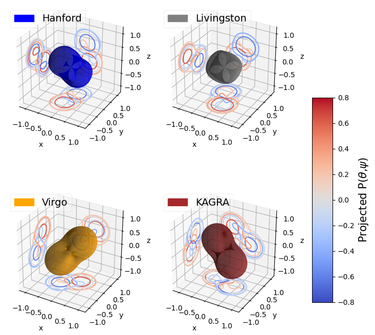
Each L-shaped interferometer has a quadrupolar antenna response. The detector’s sensitivity to a gravitational wave depends on the wave’s sky position and polarization through the antenna pattern functions $F_+(\theta, \phi, \psi)$ and $F_\times(\theta, \phi, \psi)$. For a single detector, the combined response is:
\[h(t) = F_+(\theta, \phi, \psi)\, h_+(t) + F_\times(\theta, \phi, \psi)\, h_\times(t)\]where $h_+$ and $h_\times$ are the two gravitational-wave polarizations and $\psi$ is the polarization angle. The combined power response $F_+^2 + F_\times^2$ has two blind directions — overhead and directly below the detector plane — from which the detector has zero sensitivity. A second detector, differently oriented, fills some of these gaps. A third detector, on a different continent and with a different arm orientation, closes most of the remaining blind spots.
The network signal-to-noise ratio (SNR) for $N$ detectors adds in quadrature:
\[\rho_\text{net} = \sqrt{\sum_{i=1}^{N} \rho_i^2}\]But the real gain from adding detectors is not raw SNR — it is duty cycle and sky coverage. If each detector operates independently with duty factor $d$, the probability that at least two detectors (the minimum for a confident detection) are simultaneously online is $1 - (1-d)^N - N\,d\,(1-d)^{N-1}$. Saleem et al. (2022) assume $d = 0.9$ (the target for Advanced LIGO at design sensitivity), giving coincident uptime of 81% for two detectors and 97% for three — a near-guarantee that at least two detectors are always online (Saleem et al. 2022).
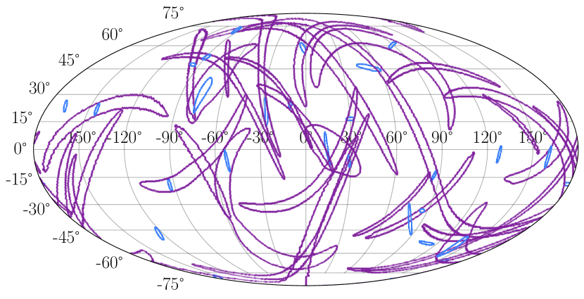
Triangulation and sky localization
Gravitational waves travel at the speed of light. A signal arriving at two detectors separated by baseline $\vec{b}$ has a time delay:
\[\Delta t = \frac{\vec{b} \cdot \hat{n}}{c}\]where $\hat{n}$ is the unit vector pointing to the source. This constrains the source to an annulus on the sky. With measurement uncertainty $\sigma_t$ in the arrival time, the annulus has angular width:
\[\delta\theta \approx \frac{c\,\sigma_t}{|\vec{b}|\,\sin\theta}\]Why two baselines are not enough
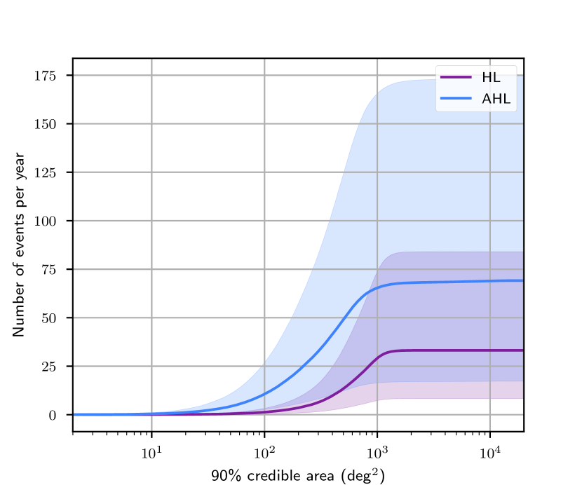
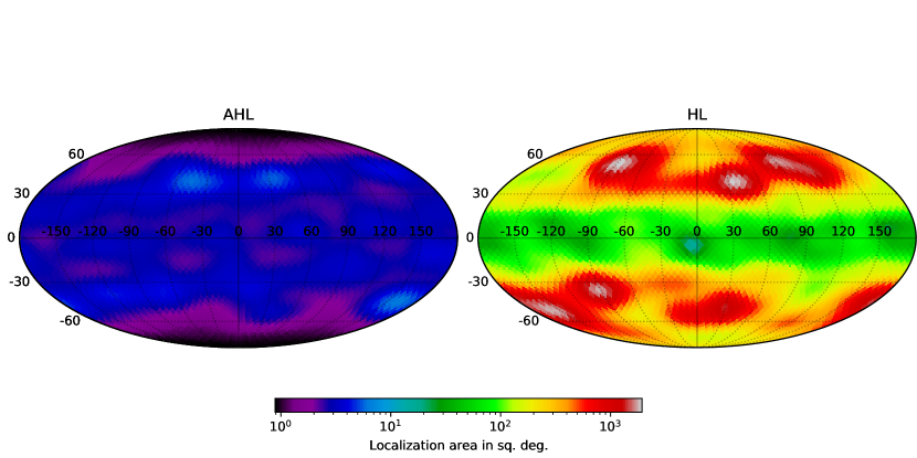
Two detectors give one baseline and one annulus — a ring on the sky. The 90% credible area for a typical binary neutron star with just LIGO Hanford and Livingston peaks around ~800 deg2 (Saleem et al. 2022), covering a significant fraction of the sky.
Adding a third detector at a different location creates three baselines. The three annuli intersect in a compact region whose area scales as:
\[\Omega_{90\%} \propto \frac{(c\,\sigma_t)^2}{A_\text{net}}\]where $A_\text{net}$ is the effective area of the triangle formed by the three detectors projected onto the plane perpendicular to the source direction. The LIGO Hanford–Livingston baseline is ~3,000 km; adding LIGO India creates two new baselines of ~8,700 km and ~9,600 km — nearly the maximum possible on Earth’s surface. This is why LIGO India’s location was chosen for triangulation leverage, not just seismic quietness.
The improvement is not incremental. Going from one baseline to three baselines typically improves sky localization by a factor of 10–100×, depending on the source’s sky position relative to the network.
GW170814 — the first event observed by three detectors (LIGO Hanford, LIGO Livingston, and Virgo) — demonstrated this directly: the 90% credible sky area shrank from ~1160 deg$^2$ (two detectors) to ~60 deg$^2$ (three detectors). LIGO India, with its longer baselines to both US sites, will do even better.
Polarization decomposition
General relativity predicts two tensor polarization states for gravitational waves: plus ($+$) and cross ($\times$). Alternative theories of gravity allow up to four additional polarizations — two vector modes and two scalar modes. Testing the polarization content of gravitational waves is a direct test of GR.
A single detector measures the linear combination $h = F_+ h_+ + F_\times h_\times$ — one equation in two unknowns. Two co-aligned detectors (like Hanford and Livingston, whose arms are nearly parallel) measure essentially the same combination, leaving the polarization states degenerate. Three non-coplanar detectors provide three independent measurements, enabling decomposition of both tensor polarizations and discrimination against non-tensorial modes.
Bayesian polarization tests
The polarization test works by computing Bayes factors between competing hypotheses:
- $\mathcal{H}_T$: signal contains only tensor ($+$, $\times$) polarizations (GR prediction)
- $\mathcal{H}_V$: signal contains only vector modes
- $\mathcal{H}_S$: signal contains only scalar modes
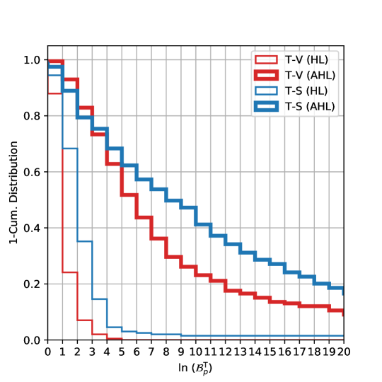
| The Bayes factor $\mathcal{B}^T_V = p(\text{data} | \mathcal{H}_T) / p(\text{data} | \mathcal{H}_V)$ quantifies the evidence for tensor vs. vector polarization. With two detectors, the Bayes factors are often inconclusive ($\ln \mathcal{B} \lesssim 3$). With three non-coplanar detectors, the AHL network produces decisive Bayes factors ($\ln \mathcal{B} \gtrsim 10$) for the majority of detected events — enough to definitively confirm or rule out non-GR polarization content. |
Saleem et al. (2022) showed that for BBH events with network SNR > 10, the AHL network produces decisively larger Bayes factors ($\ln \mathcal{B}^T_V > 10$) for the majority of detected events, while the HL network rarely achieves decisive evidence.
Quantitative science gains
The Science Case paper (Saleem et al. 2022) quantified the improvements from adding LIGO India to the Hanford–Livingston network (HL → AHL) using population-informed simulations:
| Metric | HL (2 detectors) | AHL (3 detectors) | Improvement |
|---|---|---|---|
| BBH median 90% sky area | 114 deg$^2$ | 9 deg$^2$ | 12× |
| BNS median 90% sky area | ~800 deg$^2$ | ~20 deg$^2$ | 40× |
| BNS detection rate | 33/yr | 69/yr | 2.1× |
| Network duty cycle ($d = 0.9$) | 81% | 97% | 1.2× |
| Pre-merger alerts ($\leq$100 deg$^2$) | rare | ~1 every 4 yr | — |
| Decisive polarization tests | minority of events | majority of events | — |
Early warning for multi-messenger astronomy
Binary neutron star mergers produce electromagnetic counterparts — kilonovae, short gamma-ray bursts, afterglows — that evolve on timescales of seconds to hours. Catching these transients early is scientifically transformative: the first minutes of a kilonova constrain the mass and velocity of the ejected neutron-rich material, directly probing the r-process nucleosynthesis that forges heavy elements like gold, platinum, and uranium.
Pre-merger early warning works because the inspiral gravitational-wave signal is detectable for minutes before merger. A BNS system enters the LIGO sensitivity band at ~20 Hz and sweeps upward, spending:
\[\tau_\text{to merger} \approx 2.2\;\text{s}\;\left(\frac{1.2\,M_\odot}{\mathcal{M}}\right)^{5/3}\left(\frac{f}{100\;\text{Hz}}\right)^{-8/3}\]where $\mathcal{M}$ is the chirp mass and $f$ is the instantaneous frequency. At 20 Hz, a canonical 1.4+1.4 $M_\odot$ BNS ($\mathcal{M} \approx 1.22\,M_\odot$) is ~150 seconds from merger — more than two minutes of advance warning. The challenge is accumulating enough SNR at low frequencies to localize the source before merger.
How early warning localization works
Early warning analysis uses only the portion of the signal accumulated up to a chosen frequency cutoff $f_\text{cut}$. Lower $f_\text{cut}$ means more advance warning but less accumulated SNR, yielding larger localization areas.
The key insight is that triangulation — the dominant localization mechanism — depends on timing precision, which improves rapidly as more signal cycles accumulate:
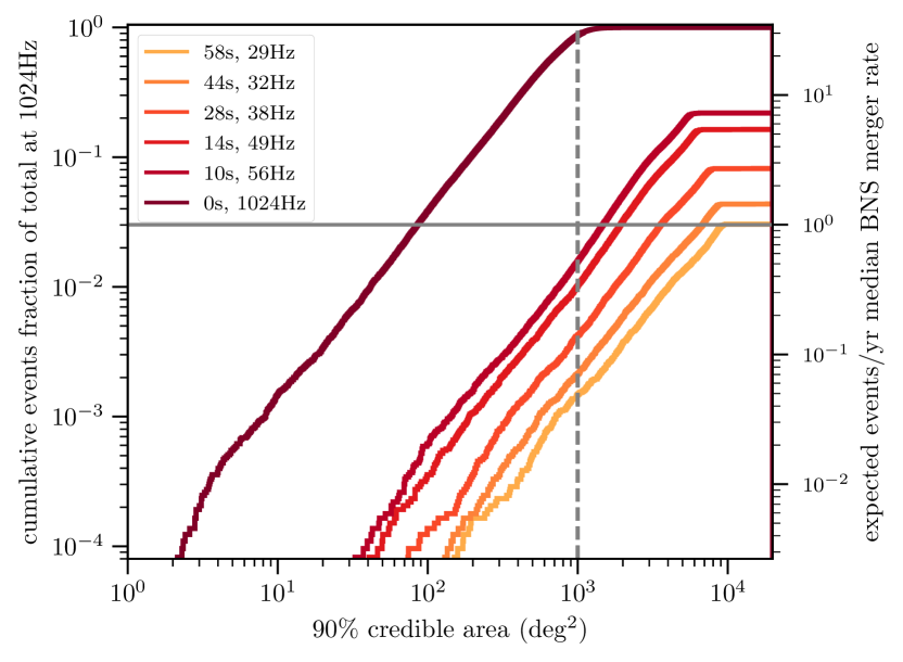
\[\sigma_t \propto \frac{1}{\rho \cdot f_\text{eff}}\]where $f_\text{eff}$ is an effective bandwidth-weighted frequency. At 30 Hz ($\sim$50 s pre-merger), a typical BNS has $\rho \approx 4$–8 in each detector. With only the HL baseline, this yields $\sigma_t \sim 10$ ms and localization areas of $\sim$10,000 deg$^2$ — useless for telescope pointing. But the AHL network, with its three long baselines, achieves $\sim$100 deg$^2$ at the same pre-merger time — approaching the field of view of wide-field survey telescopes.
Saleem et al. (2022) found that the AHL network dramatically outperforms HL for pre-merger localization. At the 1000 deg$^2$ threshold, AHL localizes ~5 BNS/yr before merger, compared to ~0.5/yr for HL. At the more stringent 100 deg$^2$ threshold, AHL achieves useful pre-merger localization for roughly 1 event every ~4 years — still rare, but impossible with HL alone.
Cosmology with standard sirens
Gravitational waves encode the luminosity distance to merging compact binaries directly in the waveform amplitude — no cosmic distance ladder required. Combined with a redshift (from an electromagnetic counterpart or statistical galaxy catalog association), each merger becomes a “standard siren” measurement of the Hubble constant $H_0$. LIGO India improves this program in two ways: three-detector polarization decomposition breaks the distance–inclination degeneracy (reducing per-event distance uncertainty), and doubling the BNS detection rate doubles the number of standard sirens per year. Combined, the AHL network can achieve ~2% $H_0$ precision within a few years at design sensitivity (Chen, Fishbach & Holz 2018).
The detector
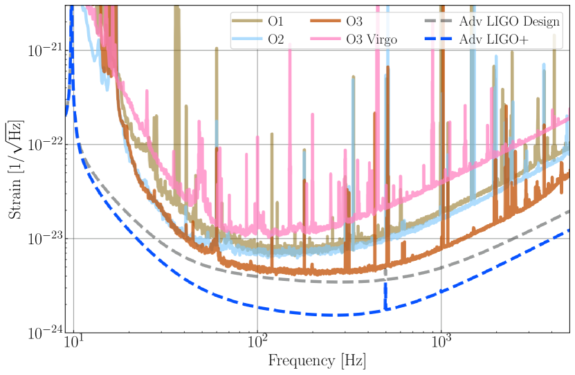
LIGO India will house a 4 km arm-length interferometer based on the Advanced LIGO A+ design — essentially the same instrument operating at LIGO Hanford and LIGO Livingston. The core technology transfer works as follows:
From LIGO US (shipped to India):
- Beam splitter and test masses (40 kg fused silica mirrors)
- Quadruple pendulum suspensions with monolithic fused-silica fibers
- Pre-stabilized laser system (200 W Nd:YAG)
- Input/output optics and modulation systems
- Squeezed light source for quantum noise reduction
Built in India:
- Ultra-high vacuum system (~8 km of beam tubes at $< 10^{-9}$ torr)
- Site infrastructure: buildings, clean rooms, electrical, HVAC
- Seismic isolation platforms (adapted for local seismic conditions)
- Operations and computing facilities
The infrastructure is being designed with headroom for future upgrades: A# (improved squeezing, better optical coatings, higher laser power) and eventually LIGO Voyager (cryogenic silicon test masses at 2 µm wavelength). The vacuum tube diameter and clean room specifications accommodate the larger optics and cryogenic systems that Voyager will require.
Network geometry and site selection
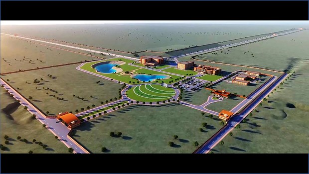
The Aundha Nagnath site in Hingoli district, Maharashtra was selected through a multi-year evaluation that balanced scientific, geological, and logistical criteria. The scientific considerations are fundamentally geometric.
Why India?
The LIGO Hanford–Livingston baseline is ~3,000 km, oriented roughly NW–SE across the United States. This single baseline has two limitations:
- Short baseline: The maximum time delay between the two sites is only ~10 ms, limiting triangulation precision
- Single orientation: Both detectors have nearly parallel arm orientations (to maximize joint detection sensitivity), which means they measure nearly the same polarization combination
LIGO India adds two new baselines:
- Hanford–India: ~8,700 km (maximum time delay ~29 ms)
- Livingston–India: ~9,600 km (maximum time delay ~32 ms)
These are nearly the maximum baselines achievable on Earth’s surface. The long baselines improve timing precision proportionally, and the different arm orientation at the Indian site means the third detector measures a different polarization combination.
Site characteristics
The Aundha Nagnath site sits on Deccan basalt — a thick, geologically stable lava flow that covers much of western India. Key characteristics:
- Low seismicity: The site is far from the Himalayan plate boundary and lies on stable cratonic rock
- Low cultural noise: Rural location with minimal road traffic and industrial activity
- Microseismic environment: Different from the US sites — the Indian Ocean microseism spectrum has different frequency content than the Pacific and Atlantic, requiring site-specific tuning of the seismic isolation system
- Monsoon considerations: The site experiences significant seasonal variation in ground motion and wind loading, requiring robust environmental isolation
Competing and complementary observatories
LIGO India is part of a global network of gravitational-wave detectors. Understanding what each observatory contributes — and what gaps remain — is essential for evaluating LIGO India’s scientific role.
Currently operating
- LIGO Hanford & Livingston (USA): 4 km arms, A+ sensitivity. The foundation of the current network. Detect ~70 events/yr at design sensitivity but with limited sky localization as a two-detector pair.
- Virgo (Italy): 3 km arms, Advanced Virgo+ sensitivity. Adds a European baseline but operates at somewhat lower sensitivity than LIGO. Together with LIGO, forms the LVK (LIGO-Virgo-KAGRA) collaboration.
- KAGRA (Japan): 3 km arms, underground, cryogenic. First detector to operate underground and with cryogenic sapphire mirrors. Currently commissioning toward design sensitivity. Adds an East Asian baseline.
Under construction
- LIGO India (India): 4 km arms, A+ sensitivity (this project). Adds the longest baselines in the network and a uniquely oriented detector plane.
Planned next-generation
- Einstein Telescope (Europe): 10 km arms, underground, triangular geometry with three nested interferometers. Combines long arms with underground operation and cryogenic technology.
Why not just build more detectors in the US?
Adding a third LIGO detector in the United States would provide limited improvement over the existing two. The reason is geometric: a third US detector would add baselines of at most ~4,000 km — comparable to the existing Hanford–Livingston baseline — and all three detectors would view the sky from similar latitudes with similar arm orientations.
LIGO India’s ~9,000 km baselines to the US sites are nearly 3× longer, yielding 3× better timing precision per baseline. More importantly, the Indian site’s latitude and longitude place it in a fundamentally different part of the detector network’s response pattern, breaking degeneracies that no number of US-based detectors could resolve.
The science case paper (Saleem et al. 2022) quantified this explicitly: an “AHLV” network (adding Virgo) improves BNS localization over AHL by only ~30%, while adding LIGO India to the HL network improves it by ~40×. The lesson: baseline diversity matters more than baseline count.
Organizational structure
LIGO India is a joint project of the Indian Initiative in Gravitational-wave Observations (IndIGO) consortium, the Indian Department of Atomic Energy (DAE), and LIGO Laboratory (operated by Caltech and MIT for the US National Science Foundation).
Nodal institutes
Four institutions lead LIGO India’s construction:
- IUCAA (Inter-University Centre for Astronomy and Astrophysics, Pune) — site characterization and survey, data analysis and computing infrastructure (~225 TF LIGO computing cluster, with planned expansion to 500+ TF), science coordination, human resource development
- DCSEM (Directorate of Construction, Services & Estate Management, Mumbai) — site acquisition, civil infrastructure and facilities design, construction management
- IPR (Institute for Plasma Research, Gandhinagar) — ultra-high vacuum systems, mechanical engineering, control and data systems (CDS)
- RRCAT (Raja Ramanna Centre for Advanced Technology, Indore) — detector hardware documentation and integration, optics R&D, 3rd-generation detector technology development, installation and commissioning
India-SURF program
The EGG group hosts students from LIGO-India partner institutions through the Caltech Summer Undergraduate Research Fellowship (SURF) program. This program trains the next generation of detector scientists and engineers who will commission and operate LIGO India — building the human capital that is as essential as the hardware.
EGG contributions
The Caltech Experimental Gravity Group contributes to LIGO India through detector science, network optimization analysis, and training programs.
-
Science metrics framework (Adhikari, Ajith, Chen, …, Read 2019) — Developed the astrophysical science metrics that quantify the scientific impact of detector network configurations, including the HLI (Hanford–Livingston–India) network. This framework provides the quantitative basis for evaluating LIGO India’s contribution to sky localization, detection rates, and parameter estimation.
-
Science case analysis (Saleem, J. Rana, …, Adhikari, Ajith, Bose 2022) — Comprehensive quantification of LIGO India’s science impact, establishing the key metrics: 12× improvement in BBH sky localization, 2× increase in BNS detection rate, and enabling decisive polarization tests. This paper is the primary science justification document for the project.
- Detector upgrades feeding LIGO India: Several active EGG research programs directly support the LIGO India upgrade path:
- Coating thermal noise research for lower-noise mirror coatings (A# and Voyager)
- LIGO Voyager cryogenic silicon interferometer design
- Adaptive optics for wavefront control at high circulating power
- RL-designed feedback controllers for commissioning and control system optimization
-
Digital twin simulations — EGG is developing digital-twin models of the LIGO interferometer control systems. These simulations can predict the behavior of a newly assembled interferometer, potentially accelerating LIGO India’s commissioning timeline by allowing control system tuning before the physical hardware is complete.
- Training pipeline — Through the India-SURF program, EGG trains graduate and undergraduate students from LIGO-India partner institutions in detector physics, control systems, and commissioning techniques.
Current status and future directions
Construction status: LIGO India is under active construction at the Aundha Nagnath site. The project received full budgetary sanction from the Indian Cabinet in April 2023 (₹2,600 crore / ~$320M) and is progressing through civil infrastructure construction. Core detector components are being prepared at LIGO US facilities for shipment.
Timeline milestones:
- Site preparation and civil construction: ongoing
- Vacuum system fabrication and installation: planned
- Detector component installation and integration: after vacuum completion
- First lock and commissioning: targeting ~2030
- Design sensitivity: targeting alignment with the O5/O6 observing run era
Open questions:
-
Commissioning timeline: What are the critical-path milestones — vacuum system completion, first lock, design sensitivity — and how do they align with the O5 and O6 observing runs?
-
Seismic environment: The Aundha Nagnath site has different seismic characteristics from Hanford and Livingston. The Deccan basalt geology and Indian Ocean microseism spectrum will require site-specific tuning of the seismic isolation system. How will the active isolation platforms be adapted for local conditions?
-
Upgrade path infrastructure: The vacuum tube diameter, clean room capacity, and cryogenic plant readiness are being specified now for compatibility with A# and Voyager. Which specific infrastructure decisions are being made to avoid costly retrofits decades from now?
-
Digital twin validation: How accurately can digital-twin simulations predict the behavior of a newly assembled interferometer, and what commissioning time savings are realistic?
-
Network scheduling: With five detectors (HLV + KAGRA + India), coordinating observing runs, maintenance windows, and upgrade schedules becomes a global optimization problem. How will the network maximize science output while allowing individual detectors to improve?
Key references
Science case and network analysis
-
Saleem, J. Rana, Gayathri, …, Adhikari, Ajith, Bose, “The science case for LIGO-India,” Class. Quantum Grav. 39, 025004 (2022). DOI:10.1088/1361-6382/ac3b99 — Comprehensive quantification of LIGO India’s science impact.
-
Adhikari, Ajith, Chen, …, Read, “Astrophysical science metrics for next-generation gravitational-wave detectors,” Class. Quantum Grav. 36, 245010 (2019). DOI:10.1088/1361-6382/ab3cff — Framework for evaluating detector network performance.
-
Abbott et al., “Prospects for observing and localizing gravitational-wave transients with Advanced LIGO, Advanced Virgo and KAGRA,” Living Rev. Relativ. 21, 3 (2018). DOI:10.1007/s41114-018-0012-9 — Network sensitivity, sky coverage, and detection rate projections.
-
Abbott et al., “GW170814: A three-detector observation of gravitational waves from a binary black hole coalescence,” Phys. Rev. Lett. 119, 141101 (2017). DOI:10.1103/PhysRevLett.119.141101 — First three-detector GW event, demonstrating triangulation and polarization.
Foundational documents
-
Iyer et al., “LIGO-India: Proposal for an interferometric gravitational-wave observatory,” LIGO-M1100296 (2011). LIGO DCC (PDF) — The original proposal document.
-
Unnikrishnan, “IndIGO and LIGO-India: Scope and Plans for Gravitational Wave Research and Precision Metrology in India,” Int. J. Mod. Phys. D 22, 1341010 (2013). DOI:10.1142/S0218271813410101 — Overview of the Indian gravitational-wave program.
Multi-messenger astronomy context
-
Abbott et al., “Multi-messenger observations of a binary neutron star merger,” Astrophys. J. Lett. 848, L12 (2017). DOI:10.3847/2041-8213/aa91c9 — GW170817: the event that launched multi-messenger GW astronomy.
-
Metzger, “Kilonovae,” Living Rev. Relativ. 20, 3 (2017). DOI:10.1007/s41114-017-0006-z — Comprehensive review of kilonova physics and the scientific case for rapid EM follow-up.
Standard sirens and cosmology
-
Schutz, “Determining the Hubble constant from gravitational wave observations,” Nature 323, 310 (1986). DOI:10.1038/323310a0 — The original standard siren proposal.
-
Abbott et al., “A gravitational-wave standard siren measurement of the Hubble constant,” Nature 551, 85 (2017). DOI:10.1038/nature24471 — First standard siren $H_0$ measurement from GW170817.
Detector technology
-
Barsotti et al., “The A+ design: Advanced LIGO with squeezed light,” LIGO-T1800042 (2018). LIGO DCC (login required) — The A+ upgrade that defines LIGO India’s initial configuration.
-
Adhikari et al., “A cryogenic silicon interferometer for gravitational-wave detection,” CQG 37, 165003 (2020). DOI:10.1088/1361-6382/ab9143 — LIGO Voyager conceptual design — the upgrade path LIGO India’s infrastructure is designed to support.
Network optimization
-
Borhanian & Sathyaprakash, “Listening to the universe with next generation ground-based gravitational-wave detectors,” arXiv:2202.11048 (2022). arXiv — Network optimization analysis for current and next-generation detectors.
-
Emma, Fernandes de Nobrega & Ashton, “Comparing advanced-era interferometric gravitational-wave detector network configurations,” arXiv:2404.16949 (2024). arXiv — Comparison of detector network configurations for sky localization and source characterization.
Further reading
For readers who want to go deeper:
-
Schutz, “Networks of gravitational wave detectors and three figures of merit,” Class. Quantum Grav. 28, 125023 (2011). DOI:10.1088/0264-9381/28/12/125023 — Rigorous treatment of network figures of merit: sky coverage, localization, and polarization.
-
Fairhurst, “Triangulation of gravitational wave sources with a network of detectors,” New J. Phys. 11, 123006 (2009). DOI:10.1088/1367-2630/11/12/123006 — Analytic framework for multi-detector sky localization.
-
Klimenko et al., “Localization of gravitational wave sources with networks of advanced detectors,” Phys. Rev. D 83, 102001 (2011). DOI:10.1103/PhysRevD.83.102001 — Coherent network analysis methods.
-
Nitz et al., “Rapid detection of gravitational waves from compact binary mergers with PyCBC Live,” Phys. Rev. D 98, 024050 (2018). DOI:10.1103/PhysRevD.98.024050 — Low-latency detection pipelines for early warning.
-
Chen, Fishbach & Holz, “A two per cent Hubble constant measurement from standard sirens within five years,” Nature 562, 545 (2018). DOI:10.1038/s41586-018-0606-0 — Forecast of $H_0$ precision from standard sirens with expanded GW networks.