LIGO Adaptive Optics
Develop adaptive optics techniques to correct thermal and alignment distortions in LIGO interferometers, improving sensitivity at high laser power.
Gallery
Research area
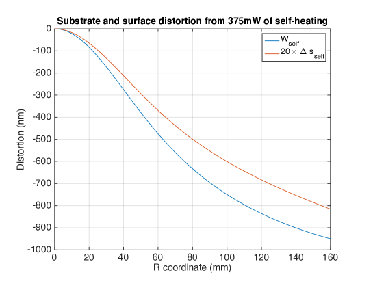
LIGO measures displacements a thousand times smaller than a proton. At design power — 750 kW circulating in each arm cavity — even 0.5 ppm of coating absorption deposits 375 mW into each test mass. The resulting thermal gradients warp the mirror surface and insert unwanted lenses into the beam path. Without correction, wavefront error reaches approximately 160 nm RMS, enough to scatter more than 1% of the beam out of the fundamental mode and severely degrade sensitivity. Active thermal compensation is not optional — it is essential infrastructure.
Contents:
- The thermal lensing problem
- The TCS toolkit
- Hartmann wavefront sensing
- Ring heaters: coarse correction
- CO2 laser projectors: fine correction
- Point absorbers: the localized threat
- Scatter and stray light
- Mode matching and higher-order modes
- Mirror birefringence and polarization effects
- FROSTI: next-generation wavefront actuation
- Phase cameras: sensing the transverse mode content
- Why adaptive optics? Competing approaches
- The cryogenic silicon path
- Our contributions
- Open questions and future directions
- Key references
- Further reading
The thermal lensing problem
A gravitational-wave interferometer is a precision optical instrument operating at extreme power levels. LIGO’s arm cavities store up to 750 kW of circulating laser power — more than a small power plant concentrated in a beam a few centimeters across. Even parts-per-million absorption in the mirror coatings converts a fraction of this into heat, creating temperature gradients that distort the optics in two distinct ways.
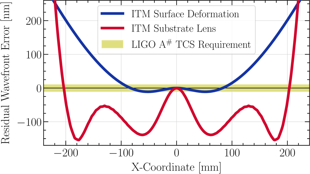
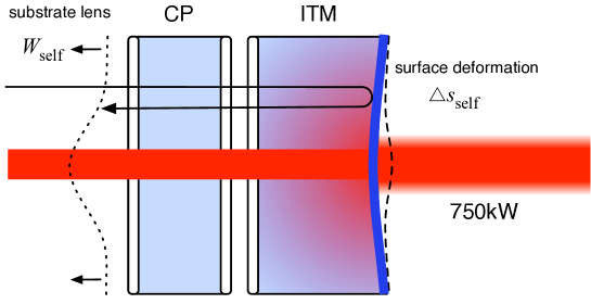
Substrate lensing. Temperature gradients in the fused silica substrate produce refractive index gradients via the thermo-optic effect ($dn/dT \approx 8.7 \times 10^{-6}$ K$^{-1}$ for fused silica). The beam passes through the input test mass (ITM) substrate, so any thermally-induced refractive index profile acts as an unwanted lens. For uniform coating absorption of 0.5 ppm at 750 kW circulating power, the resulting thermal lens in the ITM has an effective focal length of roughly 7 km — comparable to the arm cavity length, and therefore catastrophic for the cavity’s mode structure.
Surface deformation. The same absorption heats the coating surface, causing thermal expansion ($\alpha = 5.5 \times 10^{-7}$ K$^{-1}$). The surface deforms into a convex bump, changing the mirror’s effective radius of curvature. Surface deformation is smaller than substrate lensing (by roughly a factor of 20 for fused silica at 1064 nm), but both effects must be corrected simultaneously.
The thermal lens in detail
The steady-state temperature distribution in a cylindrically symmetric test mass heated by a Gaussian beam of power $P_\text{abs}$ and radius $w$ follows from solving the heat equation with appropriate boundary conditions (Hello & Vinet 1990). For the substrate thermal lens, the key quantity is the optical path length change:
\[\Delta \text{OPL}(r) = \frac{dn}{dT} \int_0^h T(r,z)\, dz\]where $h$ is the substrate thickness and $r$ is the radial coordinate. The wavefront distortion is then the difference $\Delta \text{OPL}(r) - \Delta \text{OPL}(0)$, which has a roughly parabolic shape for $r < w$ (defocus) with higher-order corrections (spherical aberration) that become significant at larger radii.
For surface deformation, the mirror sag is:
\[\delta s(r) = \alpha(1+\nu) \int_0^h T(r,z)\, dz\]where $\nu \approx 0.17$ is Poisson’s ratio for fused silica. The ratio of substrate lensing to surface deformation is approximately:
\[\frac{\Delta \text{OPL}_\text{substrate}}{\delta s} \approx \frac{dn/dT}{\alpha(1+\nu)} \approx \frac{8.7 \times 10^{-6}}{5.5 \times 10^{-7} \times 1.17} \approx 13.5\]This ratio explains why the substrate thermal lens dominates: fused silica has an unusually high thermo-optic coefficient relative to its thermal expansion.
The TCS toolkit
Advanced LIGO’s Thermal Compensation System (TCS) comprises three interlocking subsystems that together reduce wavefront error by a factor of 30. The system architecture places sensors and actuators at every test mass, with separate correction strategies for coarse (axisymmetric) and fine (spatially resolved) aberrations.
The logic is layered:
- Hartmann wavefront sensors measure the thermal state with 1.35 nm sensitivity
- Ring heaters provide coarse, axisymmetric correction (161 nm -> 52 nm RMS)
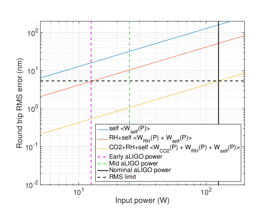
- CO2 laser projectors provide fine, spatially resolved correction (52 nm -> 5.4 nm RMS)
At full design power, the three layers together reduce wavefront error from ~160 nm to ~5 nm RMS — a factor of 30x improvement.
Hartmann wavefront sensing
The Hartmann sensor is the TCS’s primary diagnostic. An array of apertures (the Hartmann plate) samples the wavefront of a probe beam that has passed through the test mass optic. By tracking the centroid shifts of the resulting spot pattern, the sensor reconstructs the full two-dimensional wavefront distortion.
Advanced LIGO uses two distinct Hartmann sensing configurations:
-
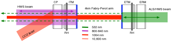
Input test masses (ITMs): Off-axis probes at 800-840 nm, injected through the anti-reflective side of the ITM and reflected from the high-reflectivity coating. These measure the combined substrate lens and surface deformation that the main beam experiences in transmission.
-
End test masses (ETMs): Green probes at 532 nm (from the arm length stabilization system), used to characterize the ETM thermal state. Since the main beam reflects from the ETM surface rather than transmitting through the substrate, ETM thermal effects are dominated by surface deformation.
The Hartmann sensors were developed by Brooks, Veitch, and Munch at the University of Adelaide. Their key innovation was achieving 1.35 nm wavefront sensitivity — roughly $\lambda/800$ at the probe wavelength — which enables tracking of absorption down to the 0.1 ppm level. This sensitivity is essential because the TCS must detect and correct thermal aberrations before they grow large enough to affect interferometer performance.
Ring heaters: coarse correction
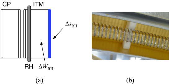
Ring heaters are nichrome wire heating elements wrapped around the barrel (circumference) of each test mass. By heating the barrel, they create a radial temperature gradient that is roughly the inverse of the gradient produced by beam absorption — concave where the beam creates convex distortion.
Key parameters:
- Power range: 0-40 W per heater
- Correction type: Axisymmetric (radially symmetric), primarily defocus
- Time constant: ~24 hours to reach thermal equilibrium
- Wavefront reduction: 161 nm -> 52 nm RMS (factor of ~3)
Why ring heaters cannot do the full job
Ring heaters apply heat at the barrel — a single radial boundary condition. The resulting temperature field inside the test mass is determined by the heat equation with this boundary condition plus the beam-heating source term. The barrel heating can only produce low-order radial modes in the temperature distribution.
The thermal lens from beam absorption, however, has a Gaussian spatial profile (matching the beam intensity). A ring heater can cancel the leading-order (parabolic/defocus) component of this Gaussian, but the residual higher-order aberrations — primarily spherical aberration — remain uncorrected. This is why the ring heater reduces wavefront error from 161 nm to 52 nm but cannot reach the 5 nm target alone.
Mathematically, decomposing the wavefront into Zernike polynomials, the ring heater corrects $Z_4$ (defocus) and partially $Z_{11}$ (primary spherical), but leaves $Z_{22}$ (secondary spherical) and higher terms essentially untouched. The CO2 projector handles the rest.
The ring heater’s 24-hour equilibration time means it operates as a very slow servo — essentially a DC offset that must be set correctly before the interferometer reaches full power. During power ramps, the ring heater tracks the slowly evolving thermal state, with the CO2 projector handling the faster transients.
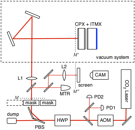
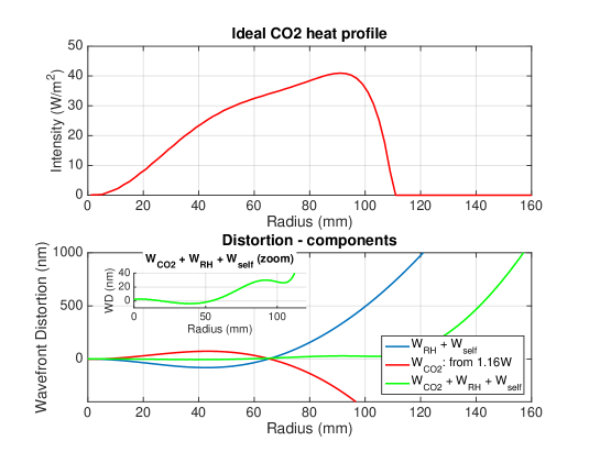
CO2 laser projectors: fine correction
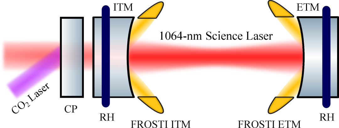
The CO2 laser projector is the fine-correction stage of the TCS. A 10.6 um CO2 laser beam is shaped using an axicon lens system to produce an annular heating pattern, which is projected onto the fused silica compensation plate (CP) positioned in front of each ITM. Fused silica is highly absorptive at 10.6 um (absorption depth ~10 um), so the CO2 beam heats only the surface layer of the CP.
Key parameters:
- Wavelength: 10.6 um (CO2 laser)
- Available power: Up to 50 W (typically ~1.2 W in use at current power levels)
- Target: Compensation plate (CP), not the test mass directly
- Correction type: Spatially shaped — primarily annular for spherical aberration correction
- Wavefront reduction: 52 nm -> 5.4 nm RMS (factor of ~10)
The choice to heat the compensation plate rather than the test mass directly is deliberate: the CP is not part of the arm cavity, so small perturbations to its thermal state do not affect the cavity finesse or stored power. The CP acts as a corrector plate — exactly analogous to a Schmidt corrector in telescope design.
Point absorbers: the localized threat
Point absorbers are microscopic contaminants (typically ~10 um diameter) embedded in or on the mirror coating surface. Each absorber acts as a localized heat source, creating a bump on the mirror surface surrounded by a shallow depression. When the main beam hits this bump, light is scattered out of the fundamental mode.
The physics is nonlinear and self-reinforcing: at higher circulating power, point absorbers heat up more, creating larger bumps, which scatter more light, which changes the cavity mode, which can redirect more power onto the absorber. This positive feedback has limited the operating power of Advanced LIGO below its design specification.

Point absorber scattering theory
A point absorber of absorption cross-section $\sigma_\text{abs}$ in a beam of intensity $I$ absorbs power $P_\text{abs} = \sigma_\text{abs} \times I$. The resulting surface bump height, for a point heat source on a half-space, scales as:
\[\delta h \propto \frac{\alpha\, P_\text{abs}}{\kappa}\]where $\alpha$ is the thermal expansion coefficient and $\kappa$ is the thermal conductivity. The bump scatters light according to the Marechal approximation: the fractional loss is $(2\pi\,\delta h/\lambda)^2$.
For fused silica ($\alpha/\kappa \approx 4 \times 10^{-7}$ m/W) with a 1 ppm absorber in a 750 kW beam, the bump is ~0.1 nm — small, but multiple absorbers add incoherently and the bumps grow nonlinearly with power.
The critical insight from Richardson, Pandey, Bytyqi, Edo, Adhikari (2022) is that the cavity geometry itself can be optimized to reduce point absorber impact. By adjusting the beam size on the mirrors (through the mirror radii of curvature), the intensity at any given absorber location decreases, reducing the bump height and the scattered power.
Brooks, Vajente, Yamamoto et al. published a comprehensive characterization of point absorbers in Advanced LIGO (Appl. Opt. 60, 4047, 2021), documenting the locations, sizes, and thermal effects of individual absorbers on the installed test masses. This data directly informed the optimization work by Richardson et al.
Scatter and stray light
Scattering from mirror surface imperfections is one of the primary mechanisms through which thermal aberrations degrade interferometer performance. Any departure from a perfect mirror surface — whether thermally induced, from polishing residuals, or from contamination — scatters light out of the fundamental Gaussian mode and into higher-order modes or diffuse directions. This scattered light is lost from the interferometer signal, and worse, some fraction of it can return as stray light after reflecting off baffles, beam tubes, or vacuum chamber walls, introducing noise through the “scattered light noise” mechanism.
The round-trip power loss in an optical cavity due to mirror surface roughness can be expressed through the power spectral density (PSD) of the surface profile. For a mirror with surface height profile $h(x,y)$, the scattering loss per reflection is:
\[\mathcal{L}_\text{scatter} = \left(\frac{4\pi}{\lambda}\right)^2 \int_{f_\text{min}}^{f_\text{max}} \text{PSD}(f)\, df\]where $f_\text{min}$ and $f_\text{max}$ are the spatial frequency bounds relevant to the cavity geometry (set by the beam size and mirror aperture, respectively). This is the standard Marechal relation applied to a single surface; in a Fabry-Perot cavity, the effective loss is the sum over all reflections.
Drori, Eichholz, Edo, Yamamoto, Enomoto, Venugopalan, Arai, Adhikari (2022) developed a unified framework for estimating cavity round-trip loss from mirror surface maps, directly applicable to engineering low-decoherence optical systems. Working at the Caltech 40 m prototype interferometer, they compared direct loss measurements with semi-analytic predictions computed from interferometric surface profile maps using intra-cavity wavefront simulations. The key result: the framework accurately predicts total cavity loss from measurable mirror properties, providing a quantitative bridge between mirror fabrication quality and interferometer optical performance.
This work is particularly relevant to thermal compensation because thermally-induced wavefront distortions contribute to the effective surface roughness PSD at spatial frequencies that the TCS must correct. If the TCS leaves residual aberrations at spatial frequencies within the scattering band, those residuals directly increase cavity loss. The 5 nm RMS target for the TCS was set, in part, by the requirement to keep thermally-induced scattering below the loss budget.
Spatial frequency regimes and their consequences
Mirror surface errors contribute differently depending on their spatial frequency:
-
Low spatial frequencies (1/aperture to ~1/beam_size, i.e., a few cycles across the mirror): These correspond to defocus, astigmatism, and spherical aberration. They couple light into low-order higher modes ($\text{TEM}{01}$, $\text{TEM}{20}$) that may resonate in the cavity. The TCS primarily corrects these.
-
Mid spatial frequencies (~1/beam_size to ~100 cm$^{-1}$): Light scattered at these angles leaves the fundamental mode but remains within the cavity aperture. It contributes to round-trip loss and can form parasitic beams that re-enter the measurement path after reflecting off vacuum chamber surfaces. This is the regime most sensitive to polishing quality.
-
High spatial frequencies (>100 cm$^{-1}$): Wide-angle scatter that exits the beam path entirely. This contributes to total integrated scatter (TIS) but not to stray light noise, because the scattered light doesn’t return to the beam path. This regime is dominated by coating micro-roughness.
The thermal compensation system operates entirely in the low spatial frequency regime. Its effectiveness is limited by the actuator spatial resolution — ring heaters can correct only the lowest modes, while the CO2 projector reaches somewhat higher spatial frequencies. FROSTI, with its SLM-based projection, promises to extend correction into the mid-spatial-frequency regime for the first time.
Mode matching and higher-order modes
In a perfect interferometer, all the laser power would circulate in the fundamental Gaussian mode ($\text{TEM}{00}$). Thermal aberrations break this: the thermally distorted mirror no longer perfectly matches the cavity eigenmode, and power leaks into higher-order transverse modes ($\text{TEM}{01}$, $\text{TEM}{10}$, $\text{TEM}{20}$, etc.).
The mode-matching efficiency is:
\[\eta_\text{MM} = \left|\int E_\text{in}^* \, E_\text{cav}\, dA\right|^2\]where $E_\text{in}$ is the input beam field and $E_\text{cav}$ is the cavity eigenmode. With perfect alignment but a thermally distorted mirror, $\eta_\text{MM}$ drops below unity, and the lost fraction appears in higher-order modes that resonate at different frequencies in the cavity.
The EGG group’s early contribution to this problem was the development of a heterodyne technique for characterizing cavity mode matching. Mueller, Shu, Adhikari, Tanner, Reitze, Sigg, Mavalvala, Camp (2000) demonstrated that by beating the fundamental mode against the first-order modes using a frequency-shifted probe beam, mode matching could be measured with high precision and in real time. Using a specially designed annular-segmented photodiode to detect cylindrical transverse modes reflected by the cavity, they achieved mode matching optimization to nearly 99.98%. This technique informed the development of later TCS sensing strategies.
A decade later, Mueller, Fulda, Adhikari, Arai, Brooks, Chakraborty, Frolov, Fritschel, King, Tanner, Yamamoto, Mueller (2015) showed that tracking the resonance frequencies of higher-order modes in the power recycling cavity provides a real-time measurement of the thermal state of the ITMs. Because the transverse mode spacing depends on the mirror radii of curvature — which shift with thermal loading — monitoring these resonances yields absorption information at the 1 ppm level without any additional hardware. This error signal can drive the TCS feedback loops directly, enabling closed-loop TCS operation during power ramps and maintaining optimal sensitivity throughout the detector’s duty cycle.
Mirror birefringence and polarization effects
The mirrors in a laser interferometer are assumed to have isotropic optical properties — the same refractive index for all polarization states. In practice, both the substrate material and the dielectric coating layers can exhibit birefringence: a difference in refractive index between two orthogonal polarization axes. For fused silica (amorphous), birefringence is typically small and arises from residual stress. For crystalline substrates like silicon or sapphire — candidates for next-generation cryogenic detectors — birefringence is intrinsic to the crystal structure.
Birefringence affects the interferometer in two ways. First, static birefringence causes the two polarization components of the laser beam to accumulate different phases as they traverse the optic, converting linearly polarized light into elliptically polarized light. This polarization rotation couples to the interferometer’s polarization-dependent response (beam splitter coatings have different reflectivities for s- and p-polarization), creating an effective optical loss. Second, and more subtly, fluctuations in birefringence — whether from thermal noise, mechanical stress, or vibration — create time-varying phase noise that directly contaminates the gravitational-wave readout channel.
Michimura, Wang, Salces-Carcoba, Wipf, Brooks, Arai, Adhikari (2024) analytically estimated the effects of birefringence and its fluctuations in mirror substrates and coatings on gravitational-wave detector performance. Their calculations established requirements for birefringence fluctuations in silicon substrate and AlGaAs coating at the $\sim 10^{-8}$ level — stringent but measurable with existing techniques. This work is directly relevant to the design of LIGO Voyager and future detectors using crystalline substrates and coatings, where birefringence management will be an integral part of the optical design.
Birefringence and squeezed light injection
Birefringence is particularly problematic for squeezed light injection. Squeezed vacuum states are prepared in a specific polarization state and injected through the output port. Any birefringence in the signal recycling mirror or the output optics rotates the squeezing ellipse relative to the interferometer readout quadrature, degrading the effective squeezing level. For 10 dB squeezing (the target for LIGO A+), the total allowable polarization rotation from all sources must be less than a few degrees.
In crystalline substrates, the birefringence depends on the crystal orientation relative to the beam propagation direction. Careful crystal axis alignment can minimize the static birefringence, but fluctuations from thermal noise remain. The Michimura et al. analysis provides the noise budget allocation needed to ensure that birefringence noise remains sub-dominant at all frequencies in the gravitational-wave band.
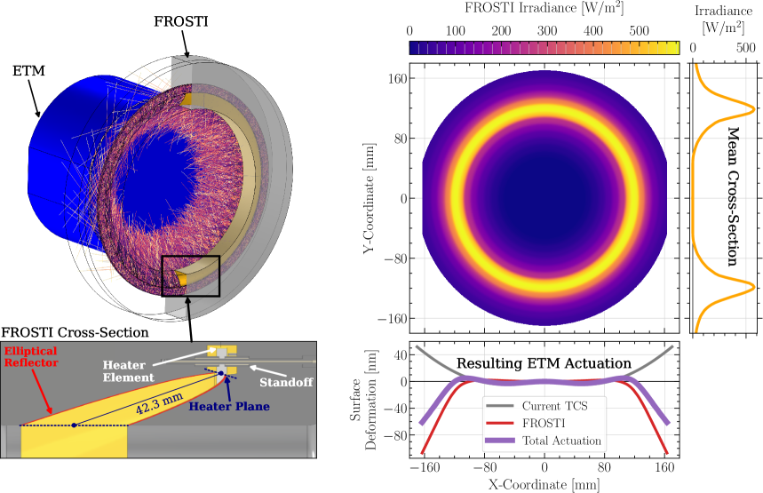
FROSTI: next-generation wavefront actuation
The current CO2 projector system has a fixed annular heating pattern — effective for the dominant aberration mode, but unable to correct arbitrary spatial distortions. FROSTI (FRee-form Optical Surface Thermal Imprinter) replaces the fixed axicon with a spatial light modulator (SLM), enabling projection of arbitrary thermal patterns onto the test mass front surface.
Key advances over the current CO2 system:
- Arbitrary spatial patterns: The SLM has thousands of individually controllable pixels, enabling correction of any aberration mode — not just the leading-order spherical term
- Direct test mass correction: FROSTI heats the test mass front surface directly, eliminating the need for a separate compensation plate
- Demonstrated at >1 MW: Tested at circulating powers nearly 5x current LIGO levels, demonstrating scalability to LIGO A# and future higher-power detectors
- Point absorber correction: The SLM can project localized heating patterns to counteract individual point absorbers — something impossible with the axicon-based CO2 system
EGG graduate student Peter Carney is a co-author on the FROSTI paper (Rosauer, Carney, Richardson et al. 2025, Optica). FROSTI is expected to be central to LIGO A# and future higher-power detectors, where circulating powers of 1.5 MW and above will make the current TCS architecture insufficient.
Phase cameras: sensing the transverse mode content
While Hartmann sensors measure the wavefront of a probe beam, phase cameras directly image the transverse mode content of the main interferometer beam. They map the interference between the carrier field and the RF sidebands, revealing how power is distributed among transverse modes in real time.
Two competing architectures are under development:
-
Optical lock-in cameras (Cao et al. 2020) — Use lock-in detection at the RF sideband frequency to extract the spatial mode profile. High sensitivity, but require specialized camera hardware.
-
CMOS time-of-flight sensors (Muniz & Ballmer 2021) — Exploit high-frame-rate commercial ToF sensors (originally developed for consumer electronics) to demodulate the beam at RF frequencies. Potentially lower cost and higher pixel count, leveraging the consumer CMOS industry.
Phase cameras complement Hartmann sensors by providing direct information about the interferometer’s optical mode content at the operating wavelength, rather than inferring the thermal state from a separate probe beam. As circulating power increases and higher-order aberrations become significant, this direct measurement becomes increasingly valuable.
Why adaptive optics? Competing approaches
Thermal compensation is not the only strategy for dealing with thermal effects. Several alternatives have been proposed — none are sufficient on their own.
Reduce absorption
The most direct approach: make mirror coatings that absorb less. Current LIGO coatings (ion-beam-sputtered $\text{Ta}_2\text{O}_5/\text{SiO}_2$ multilayers) achieve ~0.5 ppm absorption — already near the material limit. The precision optical coatings effort explores alternative materials (crystalline AlGaAs, amorphous silicon), but even at 0.1 ppm, the thermal lens at 750 kW circulating power would still exceed tolerance without active correction. Absorption reduction helps but cannot eliminate the need for TCS.
Increase beam size
Larger beams spread the absorbed power over a wider area, reducing the peak temperature rise and the thermal lens curvature. The relationship is roughly $\Delta T_\text{peak} \propto P_\text{abs}/w^2$. This is the motivation behind flat-top (mesa) beam proposals and the exploration of higher-order Laguerre-Gauss modes. However, larger beams require larger mirrors (to keep diffraction losses low), which increases coating thermal noise — the dominant noise source at mid-frequencies. There is a fundamental trade-off between thermal lensing and coating thermal noise.
Use materials with lower thermo-optic coefficient
Fused silica’s $dn/dT \approx 8.7 \times 10^{-6}$ K$^{-1}$ is the root cause of the dominant substrate lensing effect. Materials with lower $dn/dT$ would reduce the thermal lens proportionally. But the choice of substrate material is constrained by many other requirements: mechanical loss (for thermal noise), optical absorption, size availability, and suspension compatibility. No alternative to fused silica meets all requirements for room-temperature operation.
Operate at cryogenic temperatures
This is the long-term solution — and it works, but requires a complete redesign of the detector (see The cryogenic silicon path below). For current and near-future room-temperature detectors (Advanced LIGO, A+, A#), active thermal compensation remains essential.
LIGO vs. Virgo TCS approaches
The Virgo detector in Italy faces the same thermal compensation challenges but has adopted somewhat different engineering solutions. Virgo uses CO2 laser heating of the compensation plates (similar to LIGO) but also employs a “central heating” system that applies a broad Gaussian CO2 beam directly to the ITM face to pre-heat the optic before the main laser power ramps up. This reduces the transient thermal lens during lock acquisition — a period when LIGO’s TCS is least effective because the ring heaters have not yet reached equilibrium. The Einstein Telescope (ET) design study explores both room-temperature (ET-HF) and cryogenic (ET-LF) instruments, each with different TCS requirements: the room-temperature ET arms will operate at even higher power than LIGO, while the cryogenic ET arms inherit the thermal advantages of silicon at 10-20 K.
The cryogenic silicon path
Future detectors — LIGO Voyager and beyond — plan to use crystalline silicon test masses cooled to 123 K. At that temperature, silicon’s thermal properties change dramatically:
| Property | Fused silica (300 K) | Silicon (123 K) | Ratio |
|---|---|---|---|
| Thermal conductivity $\kappa$ | 1.38 W/m/K | ~700 W/m/K | 500x |
| Thermal expansion $\alpha$ | $5.5 \times 10^{-7}$ K$^{-1}$ | ~0 (CTE zero crossing) | -> 0 |
| Thermo-optic $dn/dT$ | $8.7 \times 10^{-6}$ K$^{-1}$ | ~$1 \times 10^{-6}$ K$^{-1}$ (suppressed) | ~9x |
The combination is transformative: thermal gradients dissipate almost immediately (high $\kappa$), surface deformation vanishes (zero $\alpha$), and the substrate thermal lens is strongly suppressed (low $dn/dT$). Together, these properties reduce thermal lensing by orders of magnitude compared to room-temperature fused silica.
Why 123 K specifically?
Silicon’s coefficient of thermal expansion passes through zero at approximately 123 K and again near 18 K. Operating at the zero crossing eliminates thermoelastic noise (a major contributor to coating thermal noise) and makes the test mass dimensionally insensitive to small temperature fluctuations. The 123 K crossing point is preferred over 18 K because it is more accessible with standard cryocooler technology and maintains adequate thermal conductivity for heat extraction.
At 123 K, silicon also has exceptionally low mechanical loss ($\phi \sim 10^{-9}$), making it an ideal substrate material for minimizing thermal noise. The LIGO Voyager design exploits all three properties — zero CTE, high $\kappa$, and low $\phi$ — simultaneously.
TCS does not disappear entirely in cryogenic detectors. Point absorbers still produce localized heating, and lock-acquisition transients — when the laser power ramps from zero to full operating level over minutes — create temporary thermal states that must be managed. But the problem becomes fundamentally easier: the thermal time constants are ~1000x shorter (silicon’s thermal diffusivity is ~1000x higher than fused silica’s), so the system responds much faster, and the steady-state distortions are far smaller.
Current TCS R&D directly informs the design requirements for these future instruments. The generative optical design project in our group addresses the automated optimization of interferometer configurations — including thermal compensation architectures — for next-generation detector designs.
Our contributions
-
Mode matching by heterodyne detection (Mueller, Shu, Adhikari, Tanner, Reitze, Sigg, Mavalvala, Camp 2000) — Developed a heterodyne technique for characterizing cavity mode matching using beat signals between the fundamental and first-order transverse modes, with a specially designed annular-segmented photodiode. Achieved mode-matching optimization to nearly 99.98%, demonstrating that real-time mode-matching diagnostics were feasible for gravitational-wave detectors.
-
Thermal state monitoring via higher-order modes (Mueller, Fulda, Adhikari, Arai, Brooks, Chakraborty, Frolov, Fritschel, King, Tanner, Yamamoto, Mueller 2015) — Demonstrated real-time tracking of higher-order mode resonances in the LIGO power recycling cavity to infer mirror absorption at the 1 ppm level. The method generates error signals suitable for direct input to the thermal compensation system, enabling closed-loop TCS operation during power ramps and maintaining optimal sensitivity throughout the detector’s duty cycle.
-
Scattering loss from mirror roughness (Drori, Eichholz, Edo, Yamamoto, Enomoto, Venugopalan, Arai, Adhikari 2022) — Developed a unified framework for estimating cavity round-trip loss from mirror surface maps at the Caltech 40 m prototype, directly applicable to engineering low-decoherence optical systems. This work quantifies how surface roughness (including thermally-induced distortions) converts to scattering loss, providing a bridge between TCS performance and squeezed-light injection efficiency.
-
Squeezed light optimization with point absorber mitigation (Richardson, Pandey, Bytyqi, Edo, Adhikari 2022) — Optimized the LIGO A+ arm cavities for reduced scattering from point absorbers and the signal recycling cavity for maximum squeezing benefit. The optimization framework treats the cavity geometry (beam size, mirror radii of curvature) as design variables and minimizes the impact of realistic fabrication and installation errors — yielding concrete design guidance for the current detector upgrade.
-
Mirror birefringence characterization (Michimura, Wang, Salces-Carcoba, Wipf, Brooks, Arai, Adhikari 2024) — Analytically estimated the effects of birefringence and its fluctuations in mirror substrates and coatings on interferometer performance. Established requirements for birefringence fluctuations in silicon substrate and AlGaAs coating at the $\sim 10^{-8}$ level. This work is particularly relevant for future detectors using crystalline substrates (silicon, sapphire), where birefringence is intrinsic to the material.
-
FROSTI (Rosauer, Carney, Richardson et al. 2025, Optica) — A next-generation wavefront actuator that projects custom thermal patterns directly onto the test mass front surface via spatial light modulation. FROSTI replaces the fixed annular CO2 projector with a programmable system capable of correcting arbitrary wavefront aberrations, including localized point absorber bumps. Demonstrated at circulating powers exceeding 1 MW — nearly 5x current LIGO levels. EGG graduate student Peter Carney is a co-author. FROSTI is expected to be central to LIGO A# and future higher-power detectors.
Open questions and future directions
-
FROSTI deployment path: FROSTI has been demonstrated at >1 MW circulating power in the laboratory. Integration into the LIGO sites requires addressing in-vacuum routing of the SLM projection system, clean room access constraints, and compatibility with the existing suspension and baffle structures. When and how this happens depends on the A# upgrade timeline.
-
Phase camera convergence: Two competing phase camera architectures — optical lock-in and CMOS time-of-flight — are under development. Which will scale to the sensing requirements of A# and beyond? The answer may depend on the consumer electronics roadmap for ToF sensors as much as on the GW detector requirements.
-
Higher-order mode control at high power: Current TCS primarily corrects low-order aberrations (defocus, astigmatism, spherical). As circulating power increases toward 1.5 MW (A#) and beyond, higher spatial frequencies in the thermal distortion become significant. Can FROSTI’s SLM address these, or are new actuation strategies needed?
-
Cryogenic TCS design: Silicon test masses at 123 K dramatically reduce thermal lensing, but lock-acquisition transients and point absorbers still require compensation. What does a TCS look like for LIGO Voyager, where thermal time constants are ~1000x shorter and the dominant effects are qualitatively different?
-
Adaptive optics for squeezed light injection: Squeezed light is injected through the output port of the interferometer. Any mode mismatch between the squeezed beam and the interferometer eigenmode degrades the squeezing level. The scattering loss framework developed by Drori et al. quantifies this coupling. Can TCS be extended to actively optimize the mode matching of the squeezed beam, not just the main laser?
-
Machine learning for TCS control: The current TCS uses simple PID-style feedback. As the number of actuator degrees of freedom increases (FROSTI’s SLM has thousands of pixels), the control problem becomes high-dimensional. Could reinforcement learning — as explored in our RL feedback control project — improve TCS performance?
Key references
Foundational theory
- Hello & Vinet, “Analytical models of thermal aberrations in massive mirrors heated by a Gaussian beam,” J. Phys. France 51, 1267-1276 (1990). DOI:10.1051/jphys:0199000510120126700 — First analytical treatment of thermal lensing in GW detector mirrors.
- Hello & Vinet, “Analytical models of transient thermoelastic deformations of mirrors heated by high power cw laser beams,” J. Phys. France 51, 2243-2261 (1990). DOI:10.1051/jphys:0199000510200224300 — Companion paper treating surface deformation and transient dynamics.
- Winkler et al., “Heating by optical absorption and the performance of interferometric gravitational-wave detectors,” Phys. Rev. A 44, 7022 (1991). DOI:10.1103/PhysRevA.44.7022 — Early analysis of thermal effects on interferometer sensitivity.
Advanced LIGO TCS
- Lawrence, Ottaway, Zucker & Fritschel, “Active thermal compensation of test masses in Advanced LIGO,” Class. Quantum Grav. 19, 1803 (2002). DOI:10.1088/0264-9381/19/7/377 — Design concept for the aLIGO thermal compensation system.
- Brooks et al., “Overview of Advanced LIGO adaptive optics,” Applied Optics 55, 8256 (2016). arXiv:1608.02934 — Comprehensive review of the full TCS as built and commissioned. Primary reference for this page.
- Brooks, Vajente, Yamamoto et al., “Point absorbers in Advanced LIGO,” Applied Optics 60, 4047 (2021). DOI:10.1364/AO.419689 — Characterization of point absorbers on installed test masses.
Point absorber physics
- Jia, Yamamoto, Kuns, Effler & Evans, “Point Absorber Limits to Future Gravitational-Wave Detectors,” Physical Review Letters 127, 241102 (2021). DOI:10.1103/PhysRevLett.127.241102 — General theory and statistical analysis of point absorber limits.
Scattering and optical loss
- Magana-Sandoval et al., “Large-angle scattered light measurements for quantum-noise filter cavity design studies,” JOSA A 29, 1722 (2012). DOI:10.1364/JOSAA.29.001722 — Scatter measurements relevant to filter cavity design for frequency-dependent squeezing.
Phase cameras
- Cao et al., “High sensitivity, high frame rate detection of optical transverse modes using an optical lock-in camera,” Opt. Express 28, 14405 (2020). DOI:10.1364/OE.384754 — Optical lock-in approach to phase imaging.
- Muniz & Ballmer, “High frame-rate phase camera for gravitational-wave detectors using a ToF image sensor,” Phys. Rev. D 104, 042002 (2021). DOI:10.1103/PhysRevD.104.042002 — CMOS time-of-flight approach.
FROSTI and next-generation TCS
- Rosauer, Carney, Richardson et al., “FROSTI: a next-generation wavefront actuator for gravitational-wave detectors,” Optica 12, 515 (2025). DOI:10.1364/optica.567608 — SLM-based arbitrary wavefront correction at >1 MW.
Birefringence
- Moriwaki et al., “Measurement of the residual birefringence of interferential mirrors using the nudged elastic band method,” Phys. Lett. A 236, 281 (1997). DOI:10.1016/S0375-9601(97)00804-0 — Early birefringence characterization in GW detector mirrors.
Cryogenic detectors
- Adhikari, Arai, Brooks, Wipf et al., “A cryogenic silicon interferometer for gravitational-wave detection,” CQG 37, 165003 (2020). DOI:10.1088/1361-6382/ab9143 — LIGO Voyager design establishing the cryogenic path that transforms the TCS problem.
Virgo TCS
- Accadia et al., “The Virgo thermal compensation system,” Class. Quantum Grav. 30, 055017 (2013). DOI:10.1088/0264-9381/30/5/055017 — Virgo’s thermal compensation implementation, providing a useful comparison to the LIGO TCS approach.
Further reading
For readers who want to go deeper:
- Ryan Lawrence, Active Wavefront Correction in Laser Interferometric Gravitational-Wave Detectors, MIT PhD thesis (2003). LIGO-P030001 — Foundational thesis on thermal compensation system design for Advanced LIGO.
- Aidan Brooks, Thermal Compensation in Advanced Gravitational-Wave Detectors, University of Adelaide PhD thesis (2016). — Comprehensive treatment of TCS design, Hartmann sensing, and CO2 projector development.
- Hiro Yamamoto, “SIS (Stationary Interferometer Simulation) manual,” LIGO-T070260. — The FFT-based simulation tool used to model thermal effects and TCS performance in LIGO cavities.
- LIGO TCS review documents on the LIGO DCC — Technical design documents and commissioning reports for the installed TCS.
Related publications
-
Determination and optimization of mode matching into optical cavities by heterodyne detection
-
In situcharacterization of the thermal state of resonant optical interferometers via tracking of their higher-order mode resonances
-
Scattering loss in precision metrology due to mirror roughness
-
Optimizing gravitational-wave detector design for squeezed light
-
Effects of mirror birefringence and its fluctuations to laser interferometric gravitational wave detectors